
Description:
This document shows you how to set up the QoS rules in a LANCOM router firewall in order for them to operate with the settings recommended for VoIP connections.
Requirements:
- LCOS as of version 7 (download latest version)
- LANtools as of version 7 (download latest version)
Procedure:
- The Diff-Serv flag generated by the VoIP application (generally EF)
- Which codec is used, as this determines the guaranteed bandwidth (e.g. G.711, G.729)
- The ports (usually port 5060 for SIP signaling)
In order for the QoS to work properly, it is important that the bandwidth values made available by the provider are specified on the Internet connection, otherwise the mechanism has no reference values!
Please note the special notes on using Unify telecommunications systems from Deutsche Telekom in the following instructions!
1) Firewall rule 1:
The first firewall rule reserves bandwidth for the SIP signaling:
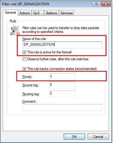
1.1) In LANconfig, open the configuration dialog for the LANCOM router and switch to the menu item Firewall/QoS → IPv4 rules → Rules.

1.2) Enter a name for the firewall rule and set the priority to 1.
1.3) The action must be set to the action object ACCEPT.

1.4) On the QoS tab you need to add a custom QoS action.

1.5) Configure a guaranteed minimum bandwidth of 1 kbps per session.

1.6) On the Stations tab set the Connection source and Connection destination to all stations.

1.7) On the Services tab, under Target services you add a new service object for the SIP service.
On the General tab, give the new service object a name.

1.8) On the Services tab, select the option Custom protocols → Edit custom protocols...
1.9) In the Ports field, enter the ports 5060 and 5061 separated by a comma.

1.10) The new service object is entered in the List of target services. Finish the configuration of the first firewall rule with OK.

2) Firewall rule 2:
The second firewall rule prioritizes the RTP data. Your IP phones must be set so that the RTP data is marked with the EF flag.
This is a presetting for many IP phones. However, just to be on the safe side you should check the configuration of your phones.
2.1) In the Firewall objects section, click the button Action objects and add a new action object in the dialog that follows.

2.2) On the General tab, give the action a descriptive name. On the Actions tab, click Add.

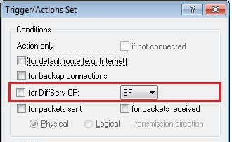
2.3) Enable the option for DiffServ-CP and select the flag EF. Close the dialog with OK.

The Unify telecommunications systems from Deutsche Telekom and also some telecommunications systems from other manufacturers send a dummy RTP packet at the beginning of a phone call, which has a wrong DiffServ tag. As a result, the created firewall rule would not apply if the DiffServ tag "EF" was used. We therefore recommend that when using these PBXs, you create an action object that does not use a DiffServ tag.
In addition, later in step 2.12, the firewall rule is restricted to the local IP address of the PBX so that it only applies to packets that are sent to the PBX.
2.4) In the Firewall objects section, click the button QoS objects and add a new QoS object in the dialog that follows.

2.5) On the General tab, give the action a descriptive name. On the Actions tab, click Add.

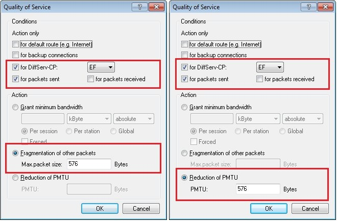
2.6) Add three QoS conditions. For each of the conditions, enable the option for DiffServ-CP and set the flag to EF.
- Configure a guaranteed minimum bandwidth. You have to define these individually depending on your scenario. In this example, a minimum bandwidth of 94 kBit / s is configured per session. According to our experience, this value has proven to be sufficient and practicable.
Note for users of Internet connections with low bandwidth:
For Internet connections with low bandwidth (guide value <50 Mbit / s downstream & 10 Mbit / s upstream), it makes sense to also configure fragmentation and PMTU reduction:
- Configure a maximum packet size of 576 bytes for the fragmentation of the remaining packets.
- Configure a reduction of the PMTU to 576 bytes.
2.7) Confirm your configuration with the OK button.

2.8) Navigate to the menu Firewall/QoS → IPv4 rules → Rules and add another firewall rule.

2.9) On the General tab, enter a descriptive name.

2.10) On the Actions tab, select the action object you created in step 2.2.

2.11) On the QoS tab, select the QoS object you created in step 2.4.

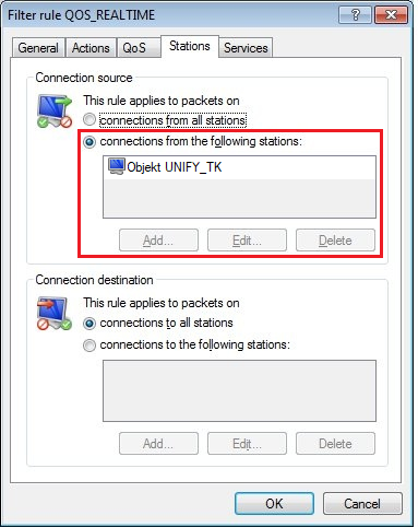
2.12) On the Stations tab, set the Connection source and Connection destination to all stations.

When using a Unify PBX from Deutsche Telekom, you must specify the PBX as the connection source so that the rule only takes traffic to the PBX into account.
In the example, a firewall object was created and used for the local IP address of the PBX.
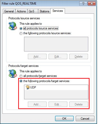
2.13) On the Services tab you set the Protocol/source services and Protocol/target services to all protocols/source services.

When using a Unify PBX from Deutsche Telekom, it makes sense to configure the UDP protocol here.
2.14) Complete the configuration of the second firewall rule with OK and write the configuration back to the LANCOM router.