
Description:
This document deals with the various error patterns that prevent a LANCOM access point from receiving a WLAN profile from a WLAN-Controller (WLC).
Requirements:
- LCOS as of version 8.50 (download latest version)
- LCOS LX as of version 5.30 (download latest version)
- LANtools as of version 8.50 (download latest version)
Potential error sources:
1) The access point cannot reach the WLAN-Ccontroller and therefore does not receive a WLAN profile.
2) The access point can reach the WLAN-Controller, but it still does not receive a WLAN profile.
The access point is not operated in “managed” mode:
Communication between an access point and a WLAN-Controller is always initiated by the access point (the LAN is searched using broadcast). In the factory default settings, an access point is configured to search automatically for a WLAN-Controller.
If the access point has already been configured, the configuration must be adapted so that the WLAN modules are managed.
Access point with LCOS:
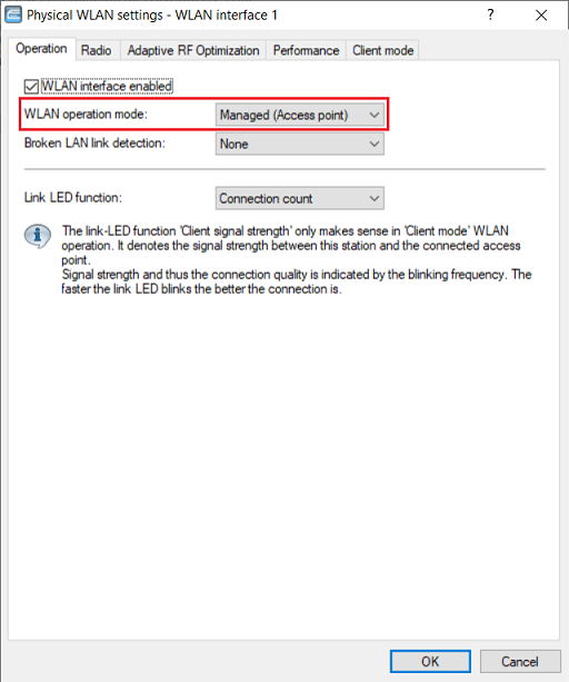
1) In LANconfig, open the access-point configuration and switch to the menu Wireless LAN → General → Physical WLAN settings → WLAN interface x. Do this individually for each WLAN module.
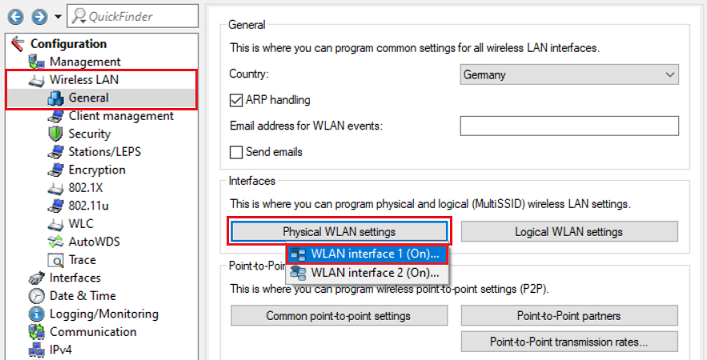
2) Make sure that the WLAN operation mode is set to Managed mode.
Access Point with LCOS LX:
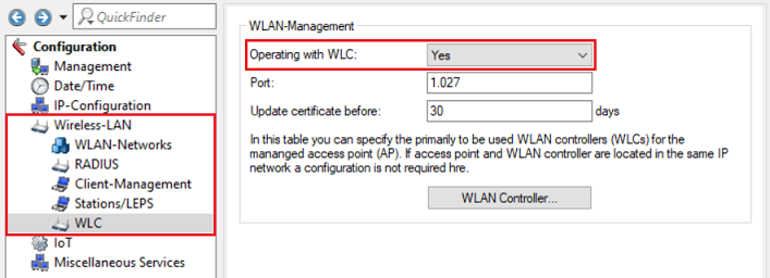
1. LANconfig:
Open the access-point configuration in LANconfig and switch to the menu Wireless-LAN → WLC and check that the parameter Operating with WLC is set to Yes.
2. WEBconfig:
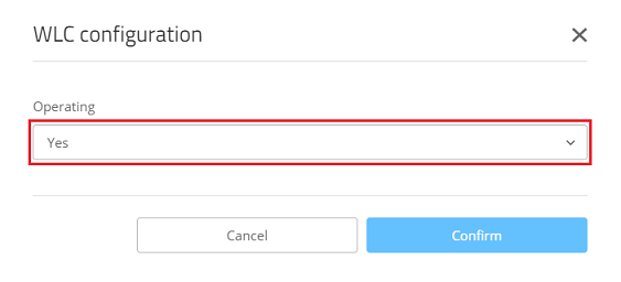
2.1) Open the configuration for the access point in WEBconfig and switch to the menu item System configuration → WLC configuration.
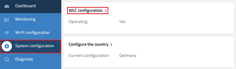
2.2) Make sure that the parameter Operating is set to Yes.
The WLAN-Controller is not set with the current time:
Since the WLAN profile for the access point is transmitted via a tunnel secured by certificates, the current time must be set on the WLAN-Controller for certificate negotiation. The time should always be obtained from one or more time servers via NTP to ensure that the correct time is set.
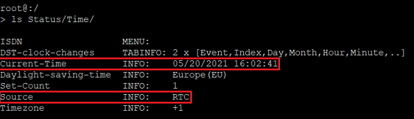
You can find out the time set on the WLAN-Controller via the system information of the LANmonitor or from the command line. The CLI command for reading the time is: ls Status/time
In this example a time is set, but it was taken from the router’s internal memory (RTC). Without synchronizing with a time server, the device time can differ from the actual time.
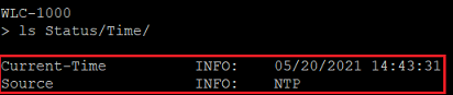
In this example the time is taken from an NTP server (NTP).
Set up time referencing via NTP:
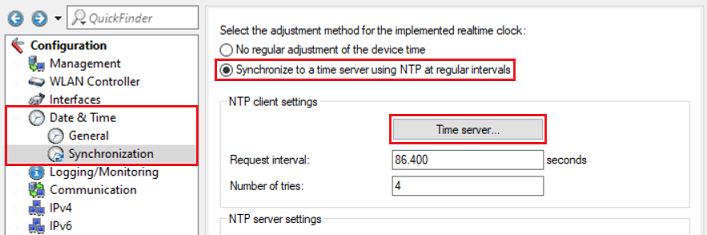
1) In LANconfig, open the configuration dialog for the WLAN-Controller and switch to the menu item Date & Time → Synchronization.
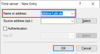
Select the option Synchronize to a time server using NTP at regular intervals and switch to the menu Time server.
2) Create a new entry and select an NTP server from the list. Alternatively, you can enter the DNS name or the IP address of another NTP server (e.g. an NTP server on the local network).
Obtaining the certificate from the WLAN-Controller via HTTP is not allowed:
The certificate is obtained via HTTP. To this end, the HTTP server on the WLAN-Controller has to be enabled and access from the LAN via HTTP has to be allowed. Furthermore, the default port 80 has to be used.
1) Allow HTTP access from the local network:
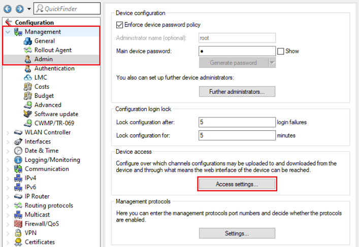
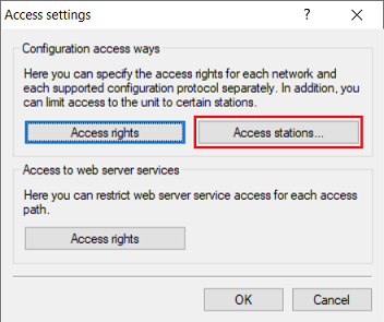
1.1) Open the configuration for the WLAN-Controller in LANconfig and switch to the menu item Management → Admin → Access settings.
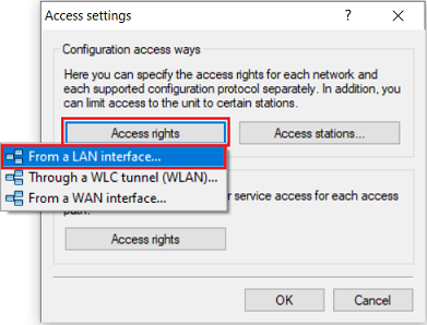
1.2) Under Configuration access ways open the menu Access rights → From a LAN interface.
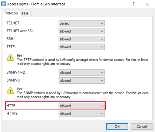
1.3) Make sure that the protocol HTTP is set to allowed.
2) Adapting the access stations (optional):
If you have stored one or more networks or IP addresses in the Access stations, you must additionally add the network containing the access points or the IP addresses (if not enabled already).
Skip this step if you don't use any access stations.
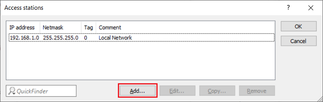
2.1) Switch to the Access stations menu.
2.2) Click on Add to create a new entry (in this example, access from the local network 192.168.1.0/24 is already allowed).
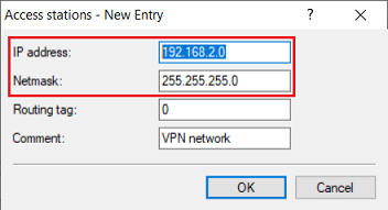
2.3) Modify the following parameters:
- IP address: Enter the network address of the network or the IP address that should have access to the WLAN-Controller (in this example, access is allowed to a separate network with the address 192.168.2.0/24).
- Netmask: Enter the netmask of the network (in this example 255.255.255.0). A single IP address is characterized by the netmask 255.255.255.255.
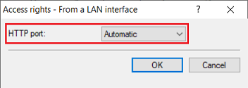
3) Check the default HTTP server setting for access from a LAN interface:
3.1) Under Access to web server services , open the menu Access rights → From a LAN interface.

3.2) Make sure that the HTTP port is set to the option Automatic. This starts the HTTP server automatically when a service connects.
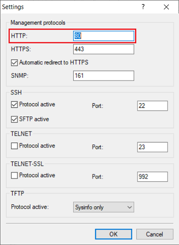
4) Use the default port for HTTP:
4.1) Navigate to the menu Management → Admin → Settings.
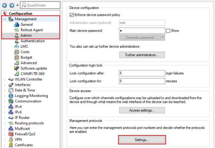
4.2) Make sure that the protocol HTTP is set to port 80.
The DNS name "WLC-Address" cannot be resolved by an access point in a remote network:
If an access point cannot find a WLAN-Controller on the local network via broadcast, it sends a DNS request with the name WLC-Address to the DNS server to discover the IP address of the WLAN-Controller. For this reason, when operating an access point that should be managed in a remote network (e.g. connected via VPN), you must ensure that the DNS server operated there (often the gateway router) is able to resolve the name WLC-Address.
To check this, first ensure that the WLAN-Controller can be reached by means of a ping to its IP address. You then have to ping the DNS name WLC-Address check whether this DNS name can be resolved by the access point.
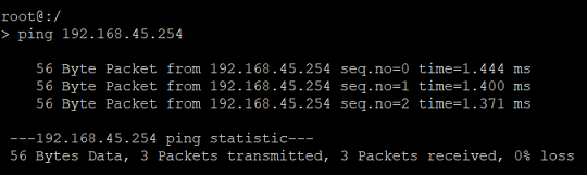
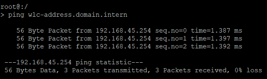
1) Checking the availability of the WLAN-Controller by pinging its IP address:
Connect to the relevant access point using the command line and use the command ping <IP address of the WLAN-Controller> to ping the WLAN-Controller and check whether it can be reached (in this example ping 192.168.45.254).
In this example, the access point is able to reach the WLAN-Controller at its IP address.
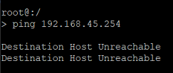
In this example, the access point cannot reach the WLAN-Controller at its IP address. → In this case, the routing between the access point and the WLAN-Controller must be checked on the corresponding routers. Furthermore, the transmission of ping packets (ICMP) must be allowed.
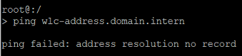
2) Checking the availability of the WLAN-Controller by pinging its DNS name WLC-Address:
Use the ping command in the form ping wlc-address.<local DNS domain> to ping the WLAN-Controller and check whether it can be reached at the DNS name WLC-Address (in this example ping wlc-address.domain.intern).
It is essential to specify the DNS domain when using the ping command, otherwise the DNS request will be discarded.
This test must be performed on the access point and not on a workstation on the network!
In this example, the access point is able to reach the WLAN-Controller at its IP address.
In this example, the DNS resolution fails because the DNS name is not known to the DNS server. → In this case, the DNS name WLC-Address must be made known to the local DNS server.
Communication between the access point and the WLAN-Controller is blocked by a firewall:
Communication between access points and the WLAN-Controller operates via CAPWAP (UDP port 1027) and certificates are obtained via HTTP (TCP port 80). Diagnostic purposes also requires the use of the protocols ICMP (ping), SSH (TCP port 22) and Telnet over SSL (TCP port 992).
If an access point is located in a remote network (e.g. connected via VPN) and a firewall regulates the communication, it may be that communication via CAPWAP and HTTP is not allowed. In this case the access point cannot communicate with the WLAN-Controller!
For this reason you must ensure that the firewall allows CAPWAP and HTTP for communication between the access point and the WLAN-Controller.
If you operate a firewall from a third party, please consult the documentation or contact the manufacturer.
Setting up the necessary firewall rules on a LANCOM R&S®Unified Firewall:
In this example, access points in a network connected via VPN (branch office) are able to communicate with the main office. The configuration described here is based on the Unified Firewall at the branch office. The configuration at the main office is analogous. There, a host object can be used for the WLAN-Controller instead of the network object, if necessary.
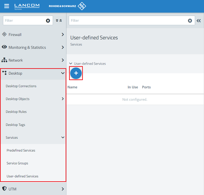
1) Open the configuration of the Unified Firewall in the browser, switch to the menu Desktop → Services → User-defined Services and click the “+” icon to create a custom service.
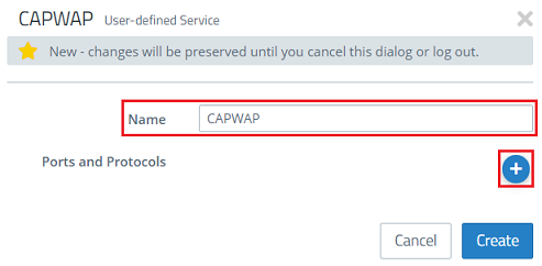
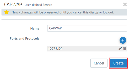
2) First, create a custom service for the CAPWAP protocol. Give it a descriptive name and click the “+” icon to open the Ports and Protocols menu.
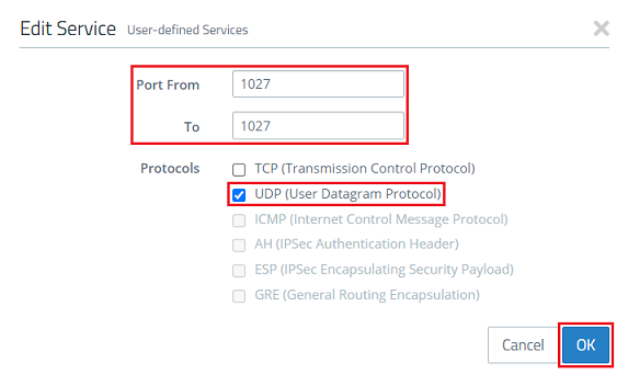
3) Modify the following parameters and then click OK:
- Set both the Port From and To to the port 1027.
- Select the protocol UDP (User Datagram Protocol).
4) Click on Create.
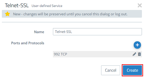
5) Then create an additional custom service for the protocol Telnet via SSL. Give it a descriptive name and click the “+” icon to open the Ports and Protocols menu.

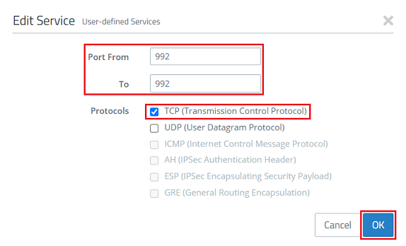
6) Modify the following parameters and then click OK:
- Set both the Port From and To to the port 992.
- Select the protocol TCP (Transmission Control Protocol) .
7) Click on Create.
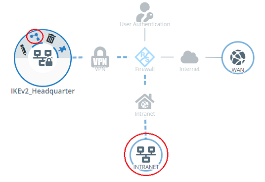
8) On the desktop, click on the VPN network, select the connection tool, and click the network object for the location with the access points.
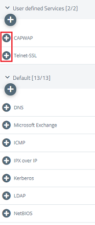
6) On the right-hand side, use the “+” icon to select the following protocols and services:
- Required for operation:
- CAPWAP (see steps 2 – 4)
- HTTP
- Required for error analysis:
- Telnet SSL (see steps 5 – 7)
- Ping
- SSH
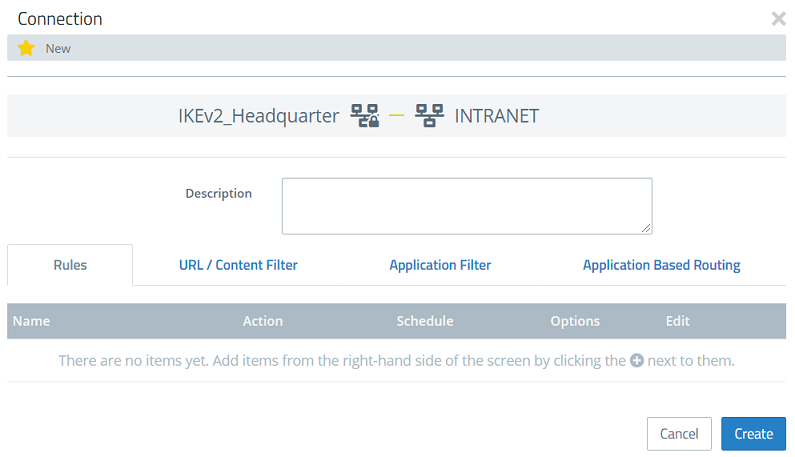
7) Click Create to create the firewall rule.
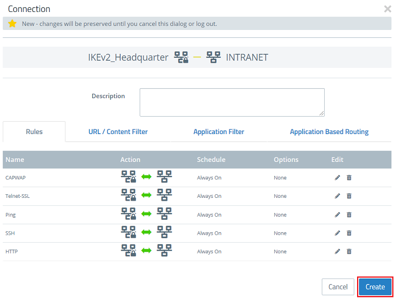
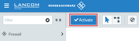
8) Implement the changes by clicking Activate.
9) If necessary, repeat the steps for the Unified Firewall at the main office.
Due to different packet sizes, transferring the certificate is not possible:
The certificate that the access point receives from the WLAN-Controller has to be transmitted in one go and must not be fragmented. To do this, the don't fragment bit is set by the WLAN-Controller. If the certificate is fragmented during transmission from another router, the certificate is no longer viable and the access point cannot be managed. Similarly, the access point cannot be managed if the certificate is not transferred.
If access points in a remote network are connected to the WLAN-Controller via VPN, disparate settings for the maximum segment sizes (MSS) may cause the certificate to be transmitted incorrectly or not at all. In this case, the MSS clamping feature has to be activated on the VPN routers.
This behavior only occurs with devices from a third-party manufacturer. LANCOM routers do not require MSS clamping to be activated.
Further steps: Creating traces
If the access point is still unable to obtain a WLAN configuration from the WLAN-Controller after checking and implementing the steps described above, further analysis requires traces to be created on the affected access point and WLAN-Controller.
When creating the traces, note that these need to be created both on the WLAN-Controller and on the affected access point at the same time as the error occurs.
Trace on the WLAN-Controller:
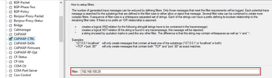
In the event of an error, use the pre-defined trace configuration to create a trace via LANtracer.

For the CAPWAP-CTRL trace, fill out the Filter field with the IP address of an affected access point (in this example 192.168.100.25). This limits the trace output to this access point.
Trace on an access point with LCOS:
In the event of an error, use the pre-defined trace configuration to create a trace via LANtracer.
Trace on an access point with LCOS LX:
Use the command line (SSH) to connect to the access point and enter the following commands. Then save the CLI output as a text file.
show diag wlan
show diag capwap
trace # capwap
The traces can be stopped by executing the command again (e.g. trace # capwap).
Send the information to LANCOM Support for further analysis:
Please send the following information to the LANCOM Support for further analysis:
- Description of the scenario and the observed behavior
- Network plan (if the access point and the WLAN-Controller are in different networks)
- Trace from the WLAN-Controller (*.lct file) including the support configuration (*.spf file)
- Trace from the access point:
- LCOS: Trace as *.lct file
- LCOS LX : Trace and the CLI output as a text file as well as the Support information (exported via WEBconfig or via SCP)