
| Seiteneigenschaften |
|---|
Description:In
diesem Artikel wird beschrieben, wie an einem bestimmten Port eines GS-3xxx Switches einem beliebigen Netzwerk-Teilnehmer eine bestimmte IP-Adresse zugewiesen wird, indem der GS-3xxx Switch als DHCP-Relay-Agent und ein LANCOM Router als DHCP-Relay-Server fungiert. Die Port-Information wird dabei vom Switch per Circuit-ID an den LANCOM Router übermitteltThis article describes how any network member is assigned a specific IP address on a specific port of a GS-3xxx switch by operating the latter as a DHCP relay agent and a LANCOM router as a DHCP relay server. The port information is transmitted from the switch to the LANCOM router by circuit ID.
Requirements:
- LCOS ab Version as of version 10.32 (download aktuelle Versionlatest version)
- LCOS SX ab Version ab Version as of version 4.00 RU9 (download aktuelle Versionlatest version)
- LANtools ab Version as of version 10.32 32 (download aktuelle Versionlatest version)
- Any web browser for accessing the webinterface of the switch
Scenario:
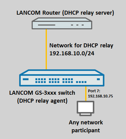
- Auf dem LANCOM Router wird ein DHCP-Relay-Server für das Netzwerk On the LANCOM router, a DHCP relay server is created for the network 192.168.10.0/24 angelegt. Das Netzwerk selber ist auf dem Router allerdings nicht vorhanden.
- Der GS-3xxx Switch fungiert als DHCP-Relay-Agent und leitet DHCP-Requests an den LANCOM Router als DHCP-Relay-Server weiter.
- . However, the network itself does not exist on the router.
- The GS-3xxx switch operates as a DHCP relay agent and forwards DHCP requests to the DHCP relay server on the LANCOM router.
- For the GS-3xxx switch, any network device connected to port 7 should receive the IP address Wenn auf dem GS-3xxx Switch ein beliebiges Netzwerk-Gerät an Port 7 angeschlossen wird, soll dieses die IP-Adresse 192.168.10.75 erhalten.
VorgehensweiseProcedure:
1. Konfiguration des ) Configuring the GS-3xxx Switchesswitch:
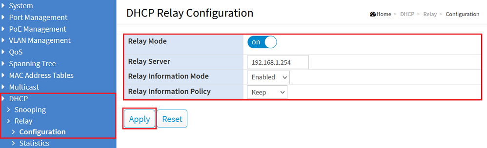
1.1 Verbinden Sie sich per Webinterface mit dem Switch, wechseln in das Menü ) Connect to the switch via the webinterface, go to the menu DHCP → Relay → Configuration, passen die folgenden Parameter an und klicken auf modify the following parameters and click Apply:
- Relay Mode: Aktivieren Sie die Funktion über den Schieberegler Activate the feature via the slider.
- Relay Server: Tragen Sie die IP-Adresse des DHCP-Relay-Servers ein (in diesem Beispiel die Enter the IP address of the DHCP relay server (in this example 192.168.1.254).
- Relay Information Mode: Wählen Sie im Dropdownmenü die Option Enabled aus. Dies erforderlich, damit die Circuit-ID übertragen wirdIn the dropdown menu select the option Enabled. This is required for transmission of the circuit ID.
- Relay Information Policy: Wählen Sie im Dropdownmenü die Option Keep aus. Wenn der Switch ein DHCP-Paket erhält, welches bereits DHCP-Relay Informationen enthält, werden diese beibehaltenIn the dropdown menu select the option Keep. If the switch receives a DHCP packet, which already contains DHCP relay information, this will be retained.
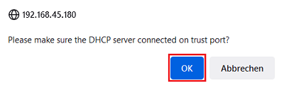
1.2 Bestätigen Sie den Hinweis mit einem Klick auf ) Acknowledge the popup note by clicking OK.
| Info |
|---|
Der Hinweis soll daran erinnern, dass bei Verwendung von DHCP-Snooping der Port zum DHCP-Server auf Trusted gesetzt sein muss. Da in diesem Szenario kein DHCP-Snooping verwendet wird, kann der Hinweis ignoriert werdenThe note is intended to remind you, that when using DHCP Snooping the port to the DHCP server has to be set to Trusted. As DHCP Snooping is not used in this scenario. the note can be ignored. |
1.3 Klicken Sie auf das rote Disketten-Symbol in der rechten oberen Ecke, um die Konfiguration als Start-Konfiguration zu speichern.) Click on the red "disk symbol" in the upper right corner to save the configuration as the start configuraton.
| Info |
|---|
The start configuration is retained even if the device is restarted or there is a power failure |
| Info |
Die Start-Konfiguration bleibt auch nach einem Neustart des Gerätes oder einem Stromausfall erhalten. |

2. Konfiguration des LANCOM Routers) Configuring the LANCOM router:
2.1 Verbinden Sie sich per LANconfig mit dem Router und wechseln in das Menü ) Use LANconfig to connect to the router and navigate to the menu IPv4 → DHCPv4 → DHCP -Netzwerkenetworks.
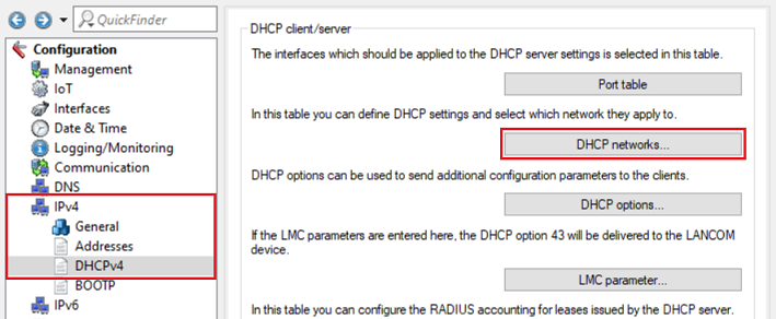
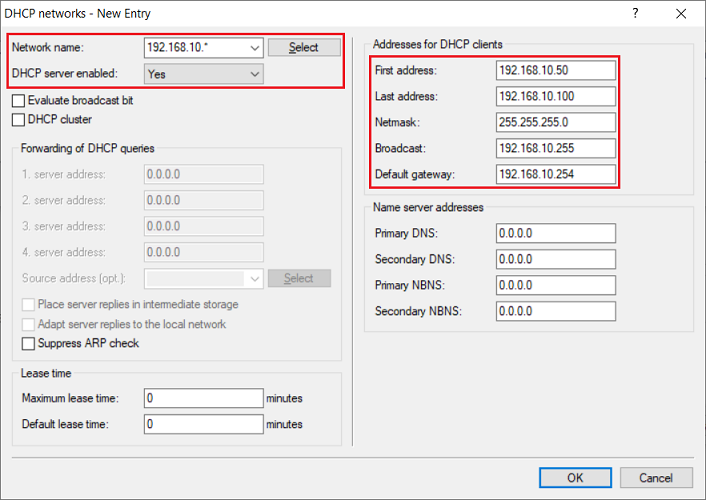
2.2 Erstellen Sie ein neues DHCP-Netzwerk und passen die folgenden Parameter an:) Create a new DHCP network and modify the following parameters:
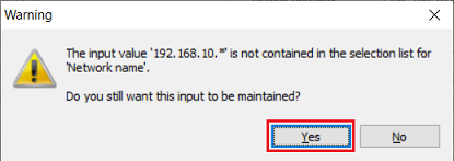
- Netzwerkname: Tragen Sie die Relay-Agent-IP-Adresse für das gewünschte Netzwerk ein. Dabei muss im letzten Oktett ein * angegeben werden (in diesem Beispiel Network name: Enter the relay agent IP address for the desired network. Here, the final octet must contain a * (in this example 192.168.10.*).
- DHCP -Server aktiviert: Wählen Sie im Dropdownmenü die Option Ja aus.server enabled: From the drop-down menu, select the option Yes.
- Erste Adresse: Tragen Sie die erste IP-Adresse des gewünschten IP-Adress-Pools ein (in diesem Beispiel First address: Enter the first IP address of the IP address pool (in this example 192.168.10.50).Letzte Adresse: Tragen Sie die letzte IP-Adresse des gewünschten IP-Adress-Pools ein (in diesem Beispiel
- Last address: Enter the last IP address of the IP address pool (in this example 192.168.10.100).
- Netzmaske: Tragen Sie die zu dem Netzwerk zugehörige Subnetzmaske ein (in diesem Beispiel Netmask: Enter the subnet mask for the related network (in this example 255.255.255.0).
- Broadcast: Tragen Sie optional die Broadcast-Adresse des Netzwerks ein (in diesem Beispiel die Optionally enter the broadcast address of the network (in this example 192.168.10.255).Standard-Gateway: Tragen Sie die IP-Adresse des Standard-Gateways in dem Netzwerk ein (in diesem Beispiel die
- Default gateway: Enter the IP address of the DHCP relay server (in this example 192.168.10.254).
| Info |
|---|
Die Angabe des IP-Adress-Pools (Erste Adresse und Letzte Adresse) sowie der Netzmaske sind bei Einrichtung eines DHCP-Relay-Servers zwingend erforderlichWhen setting up a DHCP relay server, it is essential that you specify the IP address pool (first address and last address) and also the netmask. |
2.3 Bestätigen Sie die Abfrage mit Ja. Dies ist erforderlich, weil das Netzwerk nicht im Router in dem Menü IP-Netzwerke angelegt ist) Confirm the dialog with Yes. This is necessary because the network is not created in the router in the menu IP networks.
| Hinweis | |||
|---|---|---|---|
| |||
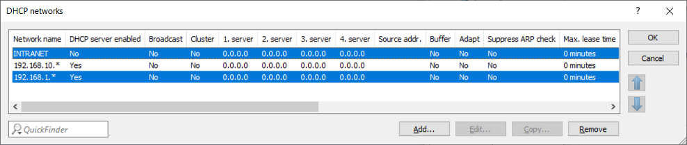
If the router is already being used as a DHCP server for local networks, the DHCP address assignment for these networks no longer works if the DHCP requests are sent to the router via the switch. This is due to the included DHCP relay information, which the regular DHCP server cannot process. In this case, a DHCP network must be created with the relay agent IP address for the local network (in this example Wird der Router bereits als DHCP-Server für lokal anliegende Netzwerke verwendet, funktioniert die DHCP-Adressvergabe für diese Netzwerke nicht mehr, wenn die DHCP-Anfragen über den Switch an den Router gesendet werden. Dies liegt an den enthaltenen DHCP-Relay-Informationen, die der reguläre DHCP-Server nicht verarbeiten kann. Daher muss in diesem Fall ein DHCP-Netzwerk mit der Relay-Agent-IP-Adresse für das lokale Netzwerk erstellt werden (in diesem Beispiel 192.168.1.*). Der Eintrag für das lokale Netzwerk (in diesem Beispiel INTRANET) muss deaktiviert werden, indem der Parameter DHCP-Server aktiviert auf Nein gesetzt wird. Hierbei ist zu beachten, dass DHCP-Anfragen dann ausschließlich über den Switch an den Router gesendet werden solltenThe entry for the local network (in this case INTRANET) must be disabled by setting the parameter DHCP server enabled to No. Note that following this, DHCP requests should only be sent to the router via the switch.
|
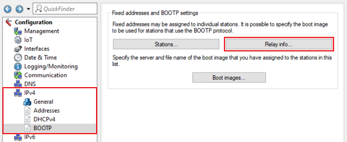
2.4 Wechseln Sie in das Menü IPv4 → ) Go to the menu IPv4 → BootP → Relay -Infoinfo.
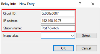
2.5 Erstellen Sie einen neuen Eintrag und passen die folgenden Parameter an) Create a new entry and adjust the following parameters:
- Circuit - ID: Tragen Sie die Circuit-ID ein, welche vom Switch an den Router übermittelt wird (in diesem Beispiel 0x000a0007Enter the circuit ID that is transmitted from the switch to the router (in this example 0x0104000a0009).
- IP address: Enter the IP address that is to be assigned to the network member at the desired switch port.
- Station name: Optionally enter a station name-Adresse: Tragen Sie die IP-Adresse ein, die dem Netzwerk-Teilnehmer an dem gewünschten Switch-Port zugewiesen werden soll.Stations-Name: Geben Sie optional einen Stations-Namen an.
| Info | ||||||||
|---|---|---|---|---|---|---|---|---|
| ||||||||
Die Circuit-ID besteht aus drei Feldern. Dabei ist zu beachten, dass die Circuit-ID im Switch binär kodiert ist, vom Router aber in Hexadezimal-Schreibweise erwartet wird. Dies ist auch in einem Ethernet-Trace (gefiltert auf BootP) zu sehen. Der Circuit-ID muss also die Zeichenfolge 0x vorangestellt werden. Weiterhin müssen die VID und die port number gegebenenfalls umgerechnet werdenThe circuit ID consists of five fields. Note that the circuit ID in the switch is encoded in binary, but is expected by the router in hexadecimal notation. This can be seen in an Ethernet trace (filtered for BootP). For this reason the circuit ID must be prefixed with the string 0x. Furthermore, the VID and the port number must be converted if necessary.
Beispiel: Ein an Port 7 angeschlossener Netzwerk-Teilnehmer im VLAN 10 soll eine bestimmte IP-Adresse erhalten. Die VID 10 ist in Hexadezimal-Schreibweise ein a. Die resultierende Circuit-ID lautet also wie folgt:
Example: A network member in VLAN 10 and connected to port 7 should be given a specific IP address. The VID 10 is in hexadecimal notation. The resulting circuit ID appears as follows:
|

2.6 Die Konfigurationsschritte auf dem Router sind damit abgeschlossen. Schreiben Sie die Konfiguration in den Router zurück6) This concludes the configuration steps on the router. Write the configuration back to the router.