
| Seiteneigenschaften |
|---|
Beschreibung:
Dieses Dokument beschreibt, wie Sie mit den LANCOM Aggregation Switches der XS-Serie ein Stacking konfigurieren können.
Voraussetzungen:
Description:
This document describes how to configure stacking on the LANCOM switches of the XS and GS-45xx series.
Requirements:
- LANCOM XS and GS-45xx series switches
- Identical firmware version on all switches in the stack
- LCOS SX as of version
- LANCOM Aggregation Switches der XS-Serie (z.B. LANCOM XS-5110F, LANCOM XS-5116QF)
- Identische Firmware-Version auf allen Switches, die zum Stack gehören sollen
- LCOS SX ab Version 5.00 (download)
- Web -Browser
- Die Switche besitzen bereits eine IP-Adresse (entweder statisch vergeben oder über einen DHCP-Server bezogen).
| Info |
|---|
| Verwenden Sie für die Verbindung der Switches ausschließlich die von LANCOM Systems unterstützen DAC-Kabel und SFP-Module. |
Wichtige Informationen zum Stacking:
| Info |
|---|
|
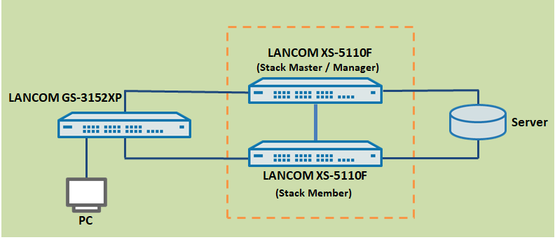
Szenario:
- In diesem Szenario werden zwei LANCOM Aggregation Switches (hier LANCOM XS-5110F) zu einem Stack zusamengefasst.
- An den Stack ist dann weitere IT-Infrastruktur angeschlossen, z.B. ein LANCOM Fully Managed Access Switch des Typs LANCOM GS-3xxx und ein Netzwerk-Server.

Vorgehensweise:
| Hinweis |
|---|
| Stellen Sie sicher, dass alle Switches welche zum Stacking gehören sollen, über die Stacking-fähigen Ports miteinander verbunden sind. |
1. Stacking auf den Switches konfigurieren:
1.1 Öffnen Sie die Konfiguration der Switches, welche im Stack operieren sollen und wechseln Sie jeweils in das Menü Stacking → Base → Port Configuration.
1.2 Wählen Sie den Port aus, welcher für das Stacking verwendet werden soll.
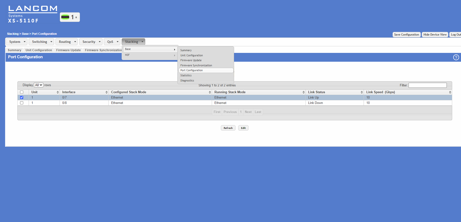
1.3 Aktivieren Sie die Stacking-Funktion, indem Sie den Interface Mode von Ethernet auf Stack ändern.
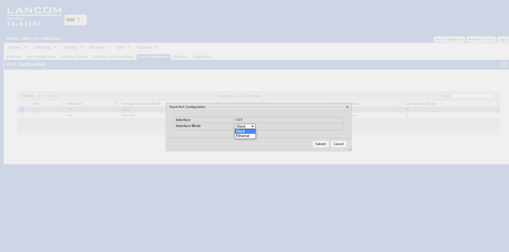
1.4 Klicken Sie auf die Schalftläche Save Configuration (in der oberen rechten Ecke des Konfigurationsfensters). Die Konfiguration wird somit bootperistent im Switch angespeichert.

1.5 Wiederholen Sie die Konfigurationschritte für jeden weiteren Switch.
- browser
- The switches need to have an IP address (either assigned statically or obtained from a DHCP server).
| Info |
|---|
| When connecting the switches, use only the DAC cables and SFP modules supported by LANCOM Systems. |
Important information about stacking:
| Info |
|---|
|
Scenario:
- This scenario collects two LANCOM aggregation switches (in this case LANCOM XS-5110F) into a stack.
- Further IT infrastructure is then connected to the stack, e.g. a LANCOM fully managed access switch of the type LANCOM GS-3xxx and a network server
Procedure:
| Hinweis |
|---|
| Explicit task steps for setting up a stacking scenario are specified in the following. We recommend that you follow this sequence. |
Step 1: Configuring stacking on the switch ports
| Info |
|---|
Do not connect the switches with the stacking cables yet but configure stacking on the switches first ! When configuring stacking the stacking ports can be operated exclusively with the native port speed. Therefore with stacking it is not possible to use an SFP module with a lower speed than the native port speed on these ports (e.g. a 1 GBit SFP module on a 10 GBit port). |
1.1 Open the configuration of the switches that are to operate in the stack and navigate to the menu Stacking → Base → Port Configuration.
1.2 Select the port to be used for stacking.
1.3 Activate the stacking feature by changing the interface mode from Ethernet to Stack.
1.4 Click the Save Configuration button (in the upper right corner of the configuration window). This saves the configuration to boot-persistent memory in the switch.
1.5 Repeat these configuration steps for each of the switches.
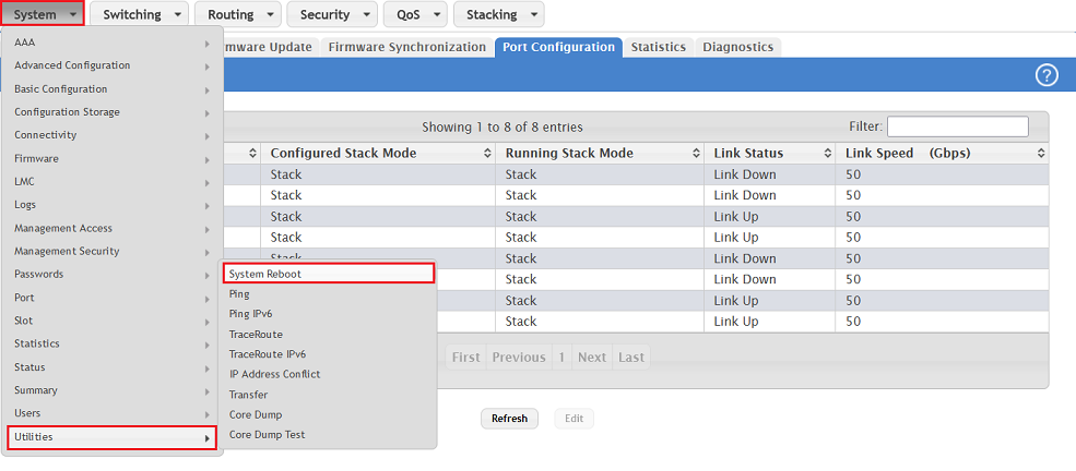
1.6 When all of the switches in the stack have been configured, they all have to be restarted (in the menu 1.6 Wenn alle am Stack beteiligten Switches konfiguriert wurden, muss jeder Switch zwingend einmal neu gestartet werden (im Menü System → Utilities → System Reboot).
| Info |
|---|
| Der gesamte Stack ist nach dem Neustart nur noch über die IP-Adresse des Stack-Master erreichbar. |

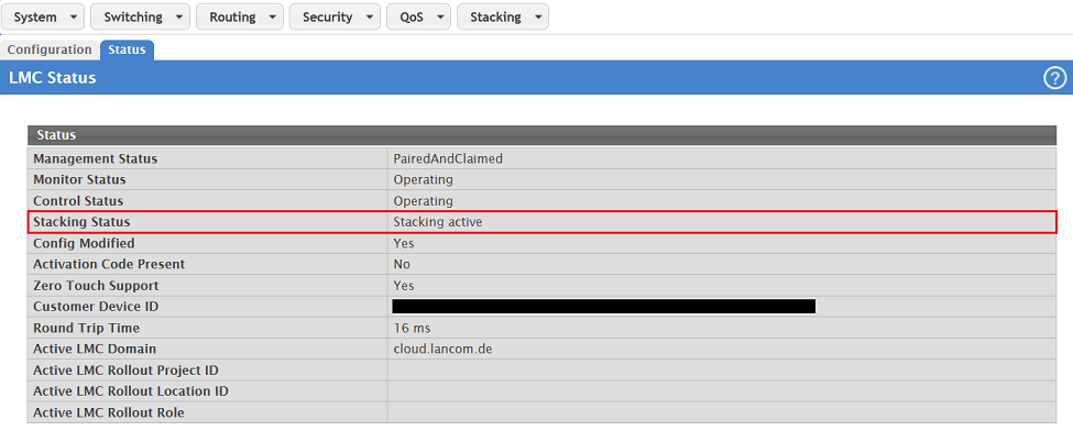
1.7 Nach einer erfolgreichen Konfiguration wird der Status des Stack in der Konfiguration angezeigt.

2. Hilfreiche Hinweise:
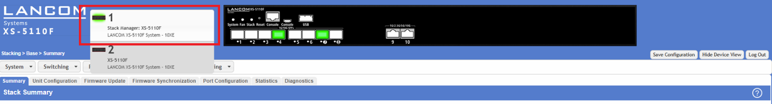
2.1 Der Status des Stacking kann im Menü Stacking → Base → Summary eingesehen werden:
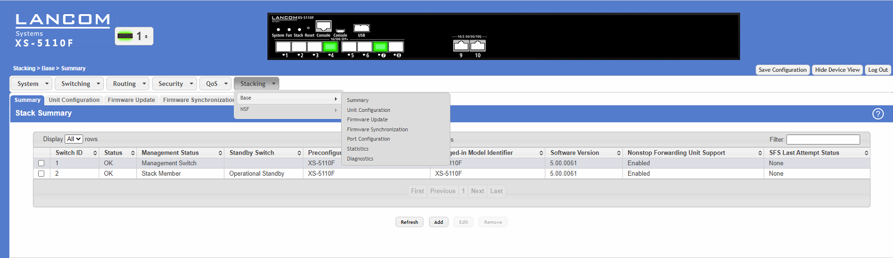
2.2 Der Port-Status kann über das Dropdown-Menü neben dem LANCOM Schriftzug auf den Stack-Membern überprüft werden.
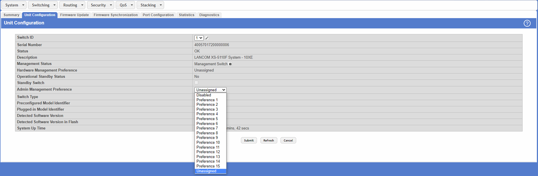
2.3 Alternativ kann die Entscheidung, welcher Stack-Member zum Master ernannt wird, durch die „Admin Management Preference“ im Menü Stacking → Base → Unitconfiguration beeinflusst werden.
| Info |
|---|
Präferenz der Einheit für die administrative Verwaltung: Bei der Wahl oder Wiederwahl eines Stapelverwalters wird die Einheit mit dem höchsten Verwaltungspräferenzwert zum Stapelverwalter. Wenn die Präferenz auf Deaktiviert gesetzt wird, ist sie für die Managerwahl nicht wählbar. |
| After restarting, the entire stack can only be reached via the IP address of the stack master. |
1.7 After successful configuration, the stacking status is displayed in the configuration.
1.8) Switch off all switches that have stacking configured on them and continue with the second step.
Step 2: Connect the cables and start the switches
2.1) Connect all of the switches involved in the stack using the ports configured in step 1.
2.2) First power up the switch that is to operate as the stack master/manager and then all of the other switches in the stack.
| Info |
|---|
|
Useful hints:
1) Manually set the stack master/manager:
You can decide which stack member is master by means of the “Admin Management Preference” in the menu Stacking → Base → Unit Configuration.
| Info |
|---|
Unit preference for admin management:
|
2) Information on changing the stack master/manager:
The following events result in a change of the stack master/manager:
- The previous stack master/manager is removed from the stack
- The previous stack master/manager is reset or switched off
- The previous stack master/manager has failed
- The number of switch stacks is increased by adding switched-on standalone switches or switch stacks
- In the case that the stack master/manager is re-selected, the new stack master/manager becomes available within seconds.
- If a new stack master/manager is chosen and the previous stack master/manager becomes available again, the previous device will not resume its role.
3) Viewing the stacking and port status:
3.1 The stacking status can be viewed in the menu Stacking → Base → Summary:
3.2 The port status on the stack members can be checked using the drop-down menu next to the LANCOM logo.