...
This article describes how VLAN is configured on a GS-3xxx series switch.
| Info |
|---|
Please note how the different VLAN tagging modes work . |
Requirements:
- LANCOM switch of the GS-3xxx series
- LANCOM router capable of managing at least three ARF networks
- LCOS as of version 8.50 ( download latest version )
- LANtools as of version 8.50 ( download latest version )
- Any web browser for accessing the web interface of the GS-3xxx
...
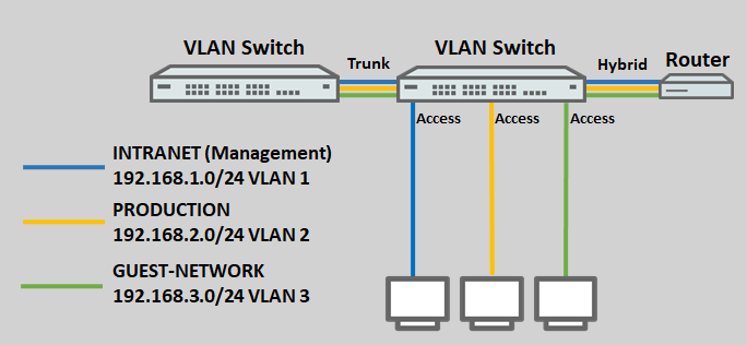
- Three networks are created on the LANCOM router with the VLAN IDs 1, 2 and 3. The management network here is the INTRANET with the VLAN ID 1.
- The logical interface LAN-1 on the router is assigned the tagging mode Hybrid.
- A further VLAN-capable switch is used, which also supports the VLANs 1 – 3. The tagging mode used on this switch is Trunk.
- The ports on the switch are assigned as follows:
- Port 1 is connected to the router.
- Port 2 is connected to the second VLAN-enabled switch.
- Port 3 is connected to an end device that should access the network INTRANET.
- Port 4 is connected to an end device that should access the network PRODUCTION.
- Port 5 is connected to an end device that should access the GUEST NETWORK.
Procedure:
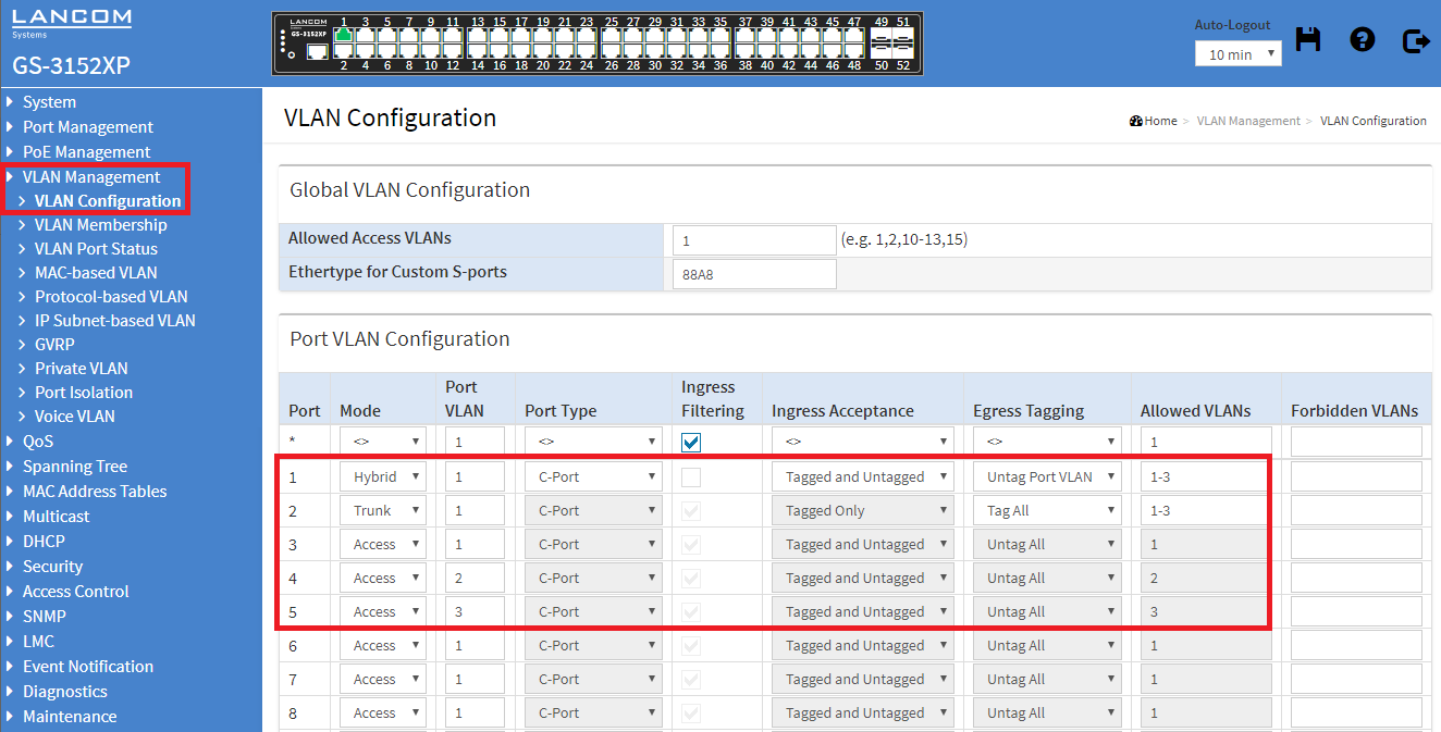
1) Connect to the web interface of the switch and navigate to the menu VLAN Management → VLAN Configuration.
2) Modify the following parameters:
...
| Hinweis |
|---|
Only the VLANs actually used must be entered for the Allowed VLANs, as otherwise this can lead to a dramatically increased CPU load of the switch. |
3) In the field Allowed Access VLANs enter all VLAN IDs, which are used by ports with the tagging mode Access (in this example the VLAN-IDs 1-3 ).
...
| Hinweis |
|---|
Only VLAN IDs which are assigned to a port with the tagging mode Access must be entered for the Allowed Access VLANs, as otherwise this can lead to a dramatically increased CPU load of the switch. |
4) After completing the VLAN configuration, click Apply to keep the changes.
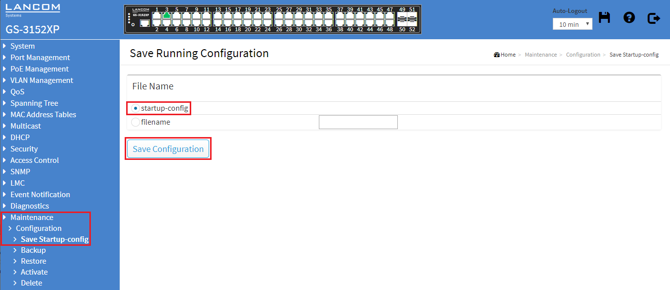
5) Change to the menu Maintenance → Configuration → Save Startup-config. Under File name, select the startup-config item and click on Save Configuration to set this configuration as the start configuration.
| Hinweis |
|---|
After restarting the switch, the start configuration is always loaded. If none is available, the default configuration will be loaded and the switch starts in its factory state. |
Troubleshooting: No communication within a VLAN on a specific switch port
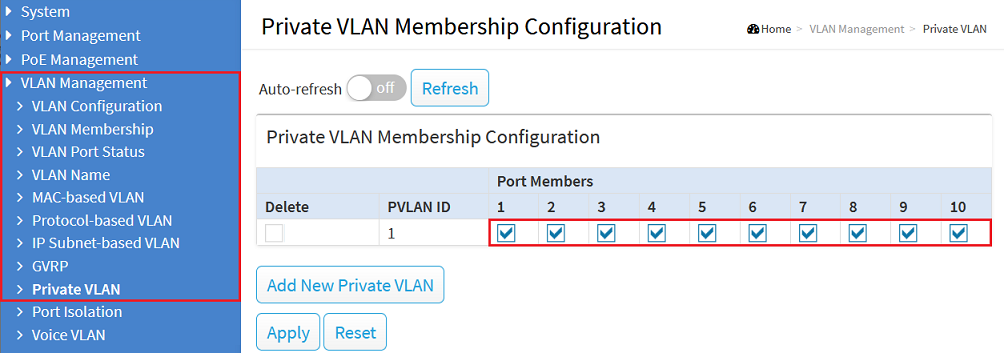
When a Private VLAN has been created, a switch port must be a member of the respective VLAN as well as the corresponding Private VLAN for the communication to be possible.
Therefore go to the menu VLAN Management → Private VLAN and make sure, that all ports are a member of the respective VLAN.
| Info |
|---|
In the default configuration all switch ports are a member of the Private VLAN 1. Therefore only the VLAN 1 is affected unless additional Private VLANs are added. |


