Description: This document outlines the parameters and functions of the "Advanced Routing and Forwarding" feature for LANCOM -Routers routers with WLAN. -Router router without WLAN and want to seperate the local networks as well please |
read  Image Removed Image Removed The aim is to restrict access between the networks networks Net 1, Net 2 and Net 3 on the LAN side of the router. - Net 1 is a network for employees and should provide access to all other networks and to the Internet.
- Net 2 is a network for visitors and should provide access to the Internet only.
- Net 3 is a server network and should not have active access to any other network; however, Net 1 should have access to these servers.
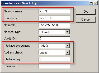
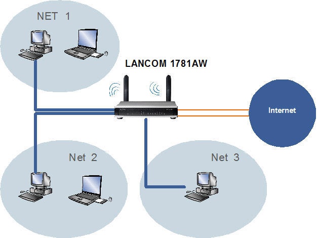 Net 1: Net 1: Interfaces LAN1 (ETH -1) and logical WLAN 1, Network ID: 172.16.1.0 Net 2: Interfaces LAN2 (ETH -2) and logical WLAN 2, Network ID: 172.16.2.0 Net 3: Interfaces LAN3 (Eth-3) and LAN4 (Eth-3), Network ID: 172.16.3.0
Procedure: LANconfig is used to perform the configuration. A A LANCOM 1781AW is used for this example scenario. - Interface tags can be allocated to the IP networks. This gives you control over the communication between the networks. Routing tags can be allocated in the routing table.
- When combined with the interface tags, these make it possible to control which route may be used by which local network.
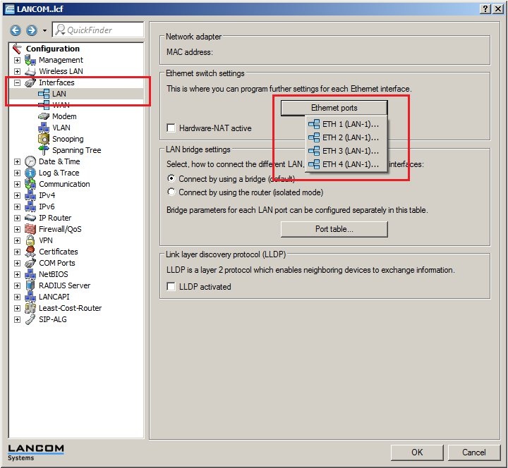
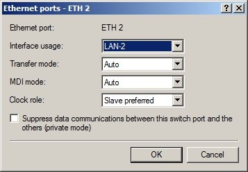
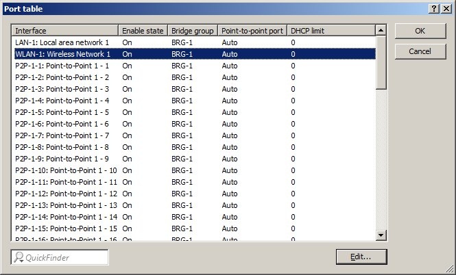
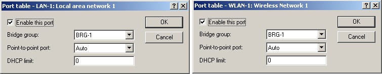
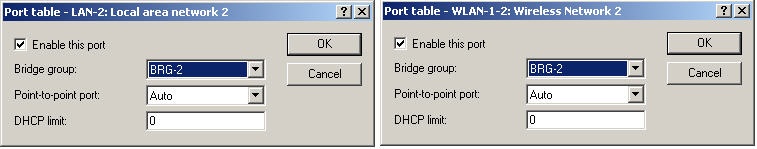
Step 1: Allocating the interfaces to the networks. 1. Open your router's configuration with LANconfig. 2. Allocate Ethernet interface 1 to the logical logical LAN-1. 3. Allocate Ethernet interface 2 to the logical logical LAN-2. 4. Allocate Ethernet interfaces 3 and 4 to the logical logical LAN-3. 5. Click Click Port - table to set up the bridge connections 6. Use bridge group group BRG-1 to link logical WLAN-1 with LAN-1. 7. Use bridge group group BRG-2 to link logical WLAN 1-2 with LAN-2. A bridge group for the interfaces interfaces LAN-3 and LAN-4 is unnecessary as these are already pooled as logical LAN-3.
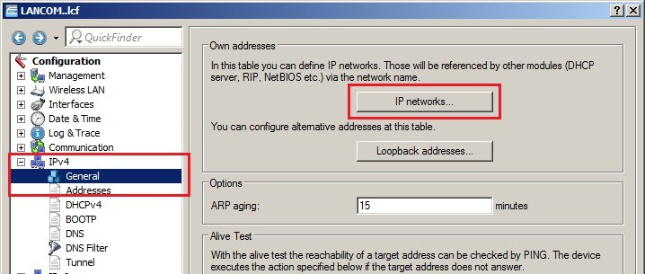
Step 2: Allocating physical interfaces and interface tags to the IP networks. Note: | Hinweis |
|---|
Do not delete the entries for the Intranet or the DMZ. |
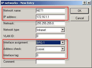
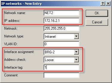
1. Open your router's configuration with LANconfig. 2. Allocate the interface and the interface tag to the IP networks. - IP networks with the interface tag '0' can access all other networks.
- IP networks with a tag in the range 1 1-65535 can only access IP networks that use the same interface tag.
3. Net 1 operates on interface BRG-1 and uses interface tag 0, i.e. it can access all other networks. 4. Net 2 operates on interface BRG-2 and is allocated interface tag 1, i.e. it cannot access any other local network. 5. Net 3 operates on interface LAN-3 and is allocated interface tag 2, i.e. it cannot access any other local network.
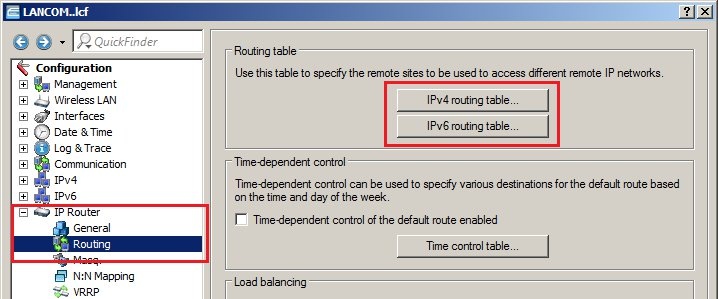
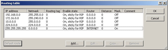
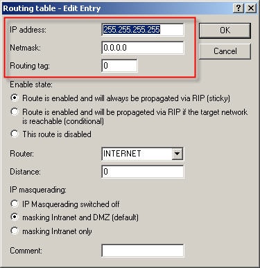
Step 3: Creating the routing entry. Clients from the networks can us all routes with routing tag 0. If the routing tag is no equal to 0 and not equal to the client’s own interface tag, the route from this network cannot be used. A default route with routing tag 0 can be used as a connection by all networks.
Completion: Configure logical logical WLAN-1 and WLAN 1-2 in order for them to provide access to the router as well. Optionally: - You can use the command Show bindings in Telnet or SSH to check that the IP addresses have been allocated to the interfaces.
- Check the configuration by establishing a connection to each LAN port, and by testing access via the two WLANs.
|