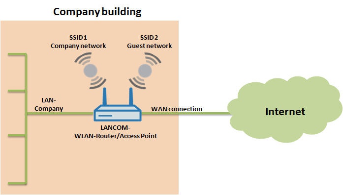
1) The WLAN clients within SSID1 (company network) are company clients. These clients have authorization for local resources within the LAN and also for Internet access.
2) The WLAN clients within SSID2 may only access the Internet.
Two scenarios are possible here:
In
the
the first scenariothe LANCOM router or access point is the gateway.
Image Removed
Image Added
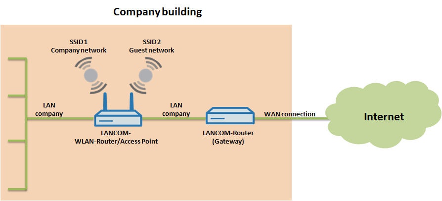
In the second scenariothe LANCOM WLAN router or access pointuses another LANCOM router as the gateway.
Note:
This
scenario
scenario does not
function
function if more than one LANCOM access
point
point is being operated. In that case you have to make use
of
of port-based VLAN.
Image Removed
Image Added
Depending on the scenario, the LANCOM WLAN routers or access points are configured differently.
Procedures
Procedure:
1) Configuring scenario 1:
For the first scenario please initially
configure
configure two IP networksand then two SSIDs. One IP-address range and one SSID are for the company WLAN clients, and the other IP-address range and corresponding SSID are for the WLAN clients that will be using the guest access.
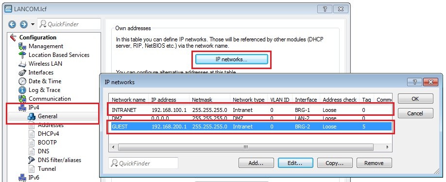
1.1) The settings for the IP address range are located under the menu
item
item IPv4 -> General-> IP networks.
Here you define, for example,
an
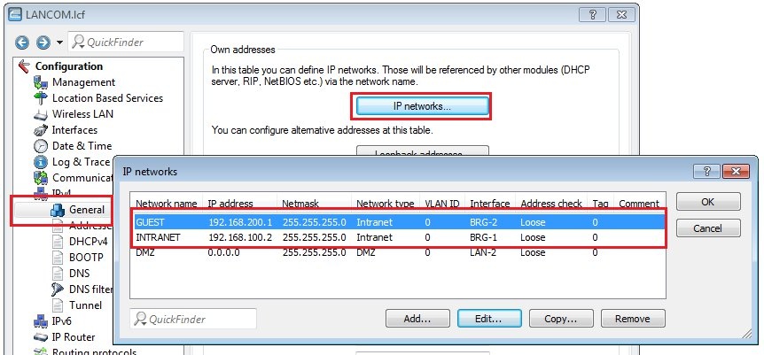
an INTRANET using the IP address 192.168.100.2and a guest network with the IP address 192.168.200.1. Under Interfaces, you assign these two networks to different BRG (bridge) groups.
By default, all interfaces are set to bridge group BRG-1.
You
You separate the networksby assigning the logical WLAN-1-2 (SSID 2) to another bridge group (BRG-2)and by setting an interface tag (5). This interface tag makes the intranet inaccessible from the guest network. Access to the guest network from the intranet remains possible.
Image Removed
Image Added
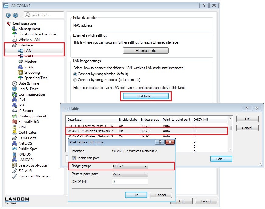
1.2) In the menu
item
item Interfaces
->
→ LAN
->
→ LAN bridge settings
->
→ Port table, you must set the bridge group BRG-2for the logical
WLAN1
WLAN-1-2.
Image Removed
Image Added
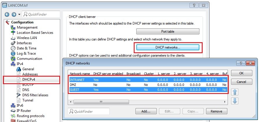
1.3) In order for WLAN clients to be given an IP address from the correct network, navigate to menu
item
item IPv4
->
→ DHCPv4
->
→ DHCP networksand set up a DHCP service for each of the networks INTRANET and GUEST.
Image Removed
Image Added
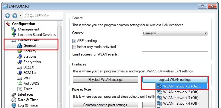
1.4) In the
menu
menu Wireless LAN
->
→ General
->
→ Logical WLAN settings, the two SSIDsmust now be set up for the networks Company network and Guest network.
In this example,
the
the SSID for the company networkis set to the logical WLAN network 1.
Image Removed
Image Added
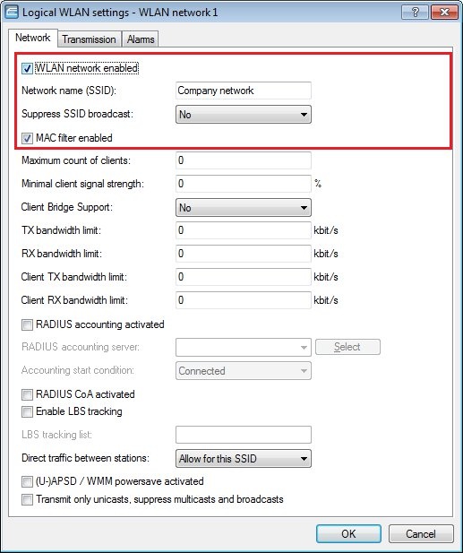
1.5) Enter a name into the
box
box Network name (SSID)(e.g. Company network). All other fields remain in the default settings.
Image Removed
Image Added
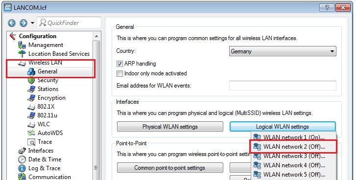
1.6) In this example,
the
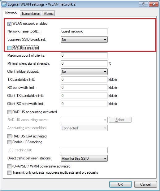
the SSID for the guest networkis set to the logical WLAN network 2.
Image Removed
Image Added
1.7) Enter a name into the
box
box Network name (SSID)(e.g. Guest network). All other fields remain in the default settings.
Image Removed
Image Added
Information:
Info
We recommend that you select WPA2 encryption in order to make the wireless LAN as secure as possible.
1.8) Write the configuration back to the LANCOM WLAN router or access point. Both networks are then able to access the Internet, but users in the guest network are unable to access the intranet.
2) Configuring scenario 2:
Information:
Info
The
The WLAN
settings
settings on the wireless router or access point
are
are identical to those in scenario 1.
2.1) In the second scenario the LANCOM WLAN router or access point uses another LANCOM router as the gateway.
The
The gateway is a part of the network INTRANETand has the IP address 192.168.100.1.
Image RemovedImage Removed
Image AddedImage Added
2.3) In addition to
the
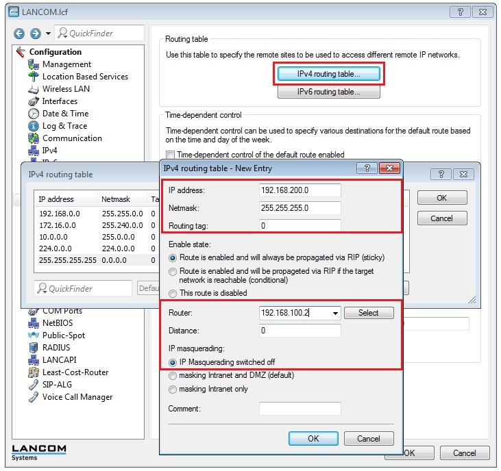
the default route, the gateway needs a return route into the guest network (192.168.200.0), which is defined on the WLAN router or access point with the IP address 192.168.100.2. The return route is configured in the menu IP router
->
→ Routing
->
→ IPv4-routing-table.
Image Removed
Image Added
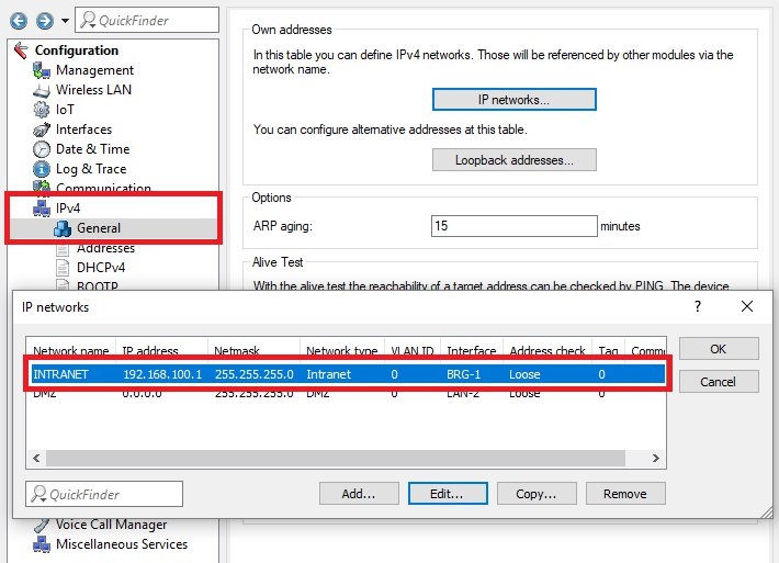
2.4) Based on the WLAN router or access-point configuration in scenario 1, the following values have to be changed.
Under
Under IPv4
->
→ General
->
→ IP networks, no interface tagis set.
Image Removed
Image Added
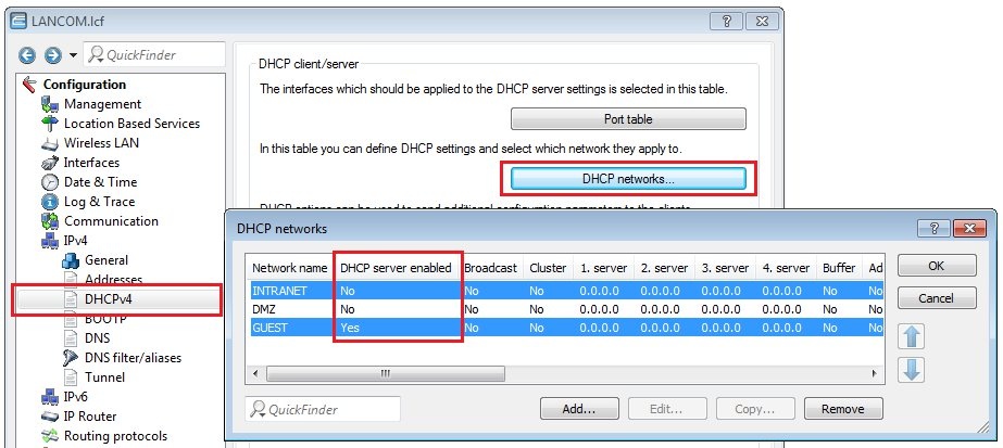
2.5) On the WLAN router or access point,disablethe DHCP functionon the INTRANET with the menu item IPv4
->
→ DHCPv4
->
→ DHCP networks.
Image Removed
Image Added
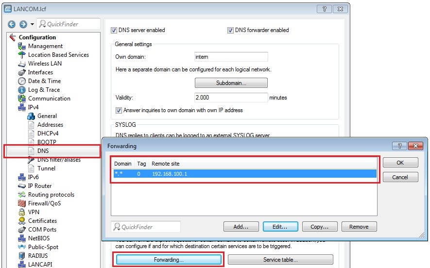
2.6)
Under
Under IPv4
->
→ DNS
->
→ Forwarding, configure the following settings to provide name resolution for the guest network.
Image Removed
Image Added
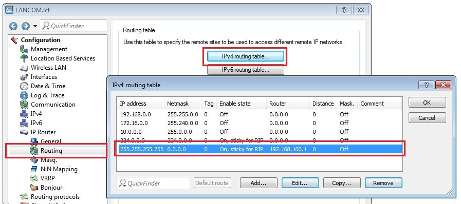
2.7) In
the
the routing table of the WLAN router or access point, a default route to the IP address of the gateway(192.168.100.1) has to be configured.
Image Removed
Image Added
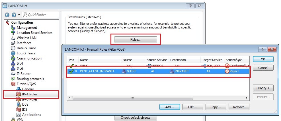
2.8) To ensure that
the
the intranet cannot be accessed from the guest network, a firewall rule must be defined in the menu item Firewall/QoS
->
→ IPv4 Rules
->
→ Rules.
Image Removed
Image Added
Information:
Info
With the firewall rule configured in this way, access from the local guest
network
network to the local INTRANET is blocked completely. If a client in the local guest
network
network requests access to a public DNS or IP address, the firewall does not interfere and access to the Internet is possible.