Versionen im Vergleich

Schlüssel

  • Diese Zeile wurde hinzugefügt.
  • Diese Zeile wurde entfernt.
  • Formatierung wurde geändert.


Seiteneigenschaften


Description:
With the ongoing migration of ISDN connections to All-IP, the ISDN connections available at sites are being converted into additional DSL connections. In order to provide this new bandwidth to the whole of the network, the router needs to be connected to the new DSL line.
If the DSL connection of the gateway is already in use, a LANCOM VDSL router can be connected upstream as a pure DSL modem. The access and VoIP data continue to be stored in the main gateway. This allows additional DSL connections to be transparently integrated into the existing scenario.
As of LCOS Version 10.20, all LANCOM VDSL routers can be switched to DSL Bridge mode. This allows the use of the devices as a pure DSL modem.


Hinweis

The Bridge mode refers only to the internal xDSL modems. If the router (additionally) has a built-in LTE modem, the LTE modem can not be operated in bridge mode!


Requirements:


Procedure:
1) Configuration steps on the router used as a modem (Modem router):
1.1) Connect the LANCOM router, which is to operate as a modem, to the VDSL port.
1.2) Open the configuration of the
VDSL
Modem router in LANconfig and go to the menu
Schnittstellen
Interfaces → LAN → Ethernet
-Ports
ports.
Image Modified
1.3)
Bearbeiten Sie den Ethernet-Port, über den Sie den Router administrieren (in diesem Beispiel ETH-1) und stellen sicher, dass diesem Port die logische Schnittstelle LAN-1 zugewiesen ist
Edit the Ethernet port to be used for administration of the router (in this example ETH 1) and make sure that the logical interface LAN-1 is assigned to it.
Image Modified
1.4)
Bearbeiten Sie einen nicht verwendeten Ethernet-Port, über den das Haupt-Gateway die Internet-Verbindung aufbauen soll (in diesem Beispiel ETH-4) und wählen bei Interface-Verwendung die Schnittstelle LAN-2 aus
Edit an unused Ethernet port to be used for the connection to the gateway router (in this example ETH 4) and select the interface LAN-2 as Interface usage
Image Modified
1.5)
Wechseln Sie in das Menü Schnittstellen
Go to the menu Interfaces → LAN → LAN
-Bridge
bridge.
Image Modified
1.6)
Stellen Sie sicher, dass die Option Verbindung über eine Bridge herstellen (Standard) ausgewählt ist und wechseln anschließend in das Menü Port-Tabelle
Make sure, that the option Connect by using a bridge (default) is selected and switch to the menu Port table afterwards.
Image Modified
1.7)
Stellen Sie sicher, dass der logischen Schnittstelle
Make sure, that no Bridge group is assigned to the logical interface LAN-1
keine Bridge-Gruppe zugewiesen ist
.
Image Modified
1.8)
Bearbeiten Sie nacheinander die in Schritt
Edit the LAN interface selected in step 1.4
ausgewählte LAN-Schnittstelle
 (in
diesem Beispiel
this example LAN-2)
sowie das xDSL-Interface
and the xDSL interface (in
diesem Beispiel
this example xDSL-1).
Weisen Sie beiden Schnittstellen eine bisher nicht verwendete Bridge-Gruppe zu (in diesem Beispiel
Assign an unused Bridge group to both interfaces (in this example BRG-2).
Image Modified Image Modified
1.9)
Die Port-Tabelle muss anschließend wie folgt aussehen
The Port table has to appear as shown below afterwards.
Image Modified
1.10)
Wechseln Sie in das Menü Schnittstellen
Go to the menu Interfaces → WAN →
Schnittstellen-Einstellungen
Interface settings → XDSL
-Modem-Betrieb
modem operation.
Image Modified
1.11)
Wählen Sie im Dropdownmenü bei Modus die Option Bridge aus anpassen müssen. Bitte erfragen Sie diese gegebenenfalls bei Ihrem Provider
In the dropdownmenu for the parameter Mode select the option Bridge.

Image Modified

Info
Je nach Provider kann es sein, dass Sie zusätzlich die Parameter VPI, VCI und den ATM-Modus

Depending on your Internet provider it is possible that the parameters VPI, VCI and the ATM mode have to be changed. Please ask your provider if necessary.


1.12

Vergeben Sie im Menü

In the menu IPv4 →

Allgemein

General → IP

-Netzwerke dem Netzwerk INTRANET eine lokale IP-Adresse aus einem bisher nicht verwendeten IP-Adressbereich (in diesem Beispiel 

networks assign an IP address from an unused IP range to the network INTRANET (in this example 192.168.3.254/24 )

und stellen sicher, dass als Schnittstelle die in Schritt 1.3 verwendete LAN-Schnittstelle LAN-1 zugewiesen ist

and make sure that the interface LAN-1 is selected (see step 1.3).


Hinweis

The assignment of an unused IP address range is mandatory. If an IP address from a local network configured on the Gateway router is entered on the Modem router and an IPoE remote site with an IP address from the local network is created on the Gateway router to ensure Management access (see step 3), the local network and the WAN (MANAGEMENT) will have the same IP address range. This will lead to routing problems! 

Image Modified
Image Modified
1.13)
Deaktivieren Sie den DHCP-Server des Gerätes im Menü
Deactivate the DHCP server of the device in the menu IPv4 → DHCPv4 → DHCP
-Netzwerke
networks.
Image Removed2.
Image Added
1.14)
Die Konfiguration des VDSL-Routers ist damit abgeschlossen. Schreiben Sie die Konfiguration in das Gerät zurück.
The configuration of the Modem router is now complete. Write the configuration back to the device.


2)
Set up the Internet connection on the main gateway (Gateway router) :
In this example, the main gateway is a LANCOM 1781EF +. Since this device does not have a built-in VDSL modem, dial-up to the Internet should be carried out via the LANCOM 730VA, which was configured as VDSL modem in step 1.
2.1) Start the setup wizard in LANconfig and select the option Set up Internet access.
Image Removed
Image Added
2.2) In this example, a new IPv4 connection is to be created.
Image Removed
Image Added
2.3) Select the Ethernet interface (External Modem / Router) setting to use an external modem.
Image Removed
Image Added
2.4) In this example, the external VDSL modem is connected to the WAN port of the LANCOM router, so WAN must be selected as the Ethernet connector in the following dialog.
Image Removed
Image Added
2.5) Select your country.
Image Removed
Image Added
2.6) Select your Internet service provider in the following dialog.
Image Removed
Image Added
2.7) In the next dialog you have to select your product.
Image Removed
Image Added
2.8) In the following dialog, enter the access data that you received from your provider.
Image Removed
Image Added
2.9) Enter the VLAN tag that your provider uses. For Deutsche Telekom VDSL connections the VLAN-ID is 7.
Image Removed
Image Added
2.10) In this example, no backup connection is used.
Image Removed
Image Added
2.11) Quit the setup wizard to set up the Internet connection with the Finish button.
The configured values are then written to the LANCOM router.
Image Removed
Image Added
2.12) After the configuration has been written back to the device, the setup wizard asks if you want to continue with another wizard.
Click No in this dialog because the configuration steps to set up the VDSL connection are complete.
2.13) Connect the
main gateway
Gateway router to the
modem
Modem router by means of an Ethernet cable.


3
.
) Make sync status of the
LANCOM modem
Modem router accessible from the network (optional) :
3.1
Einrichtung der
  • Verwenden Sie dabei einen noch freien Ethernet-Port, der von dem in Schritt 2.4 gewählten Port abweicht (in diesem Beispiel ETH-4).

Image Removed 

Vergeben Sie in diesem Schritt eine IP-Adresse samt Subnetzmaske aus dem in Schritt 1.12 vergebenen IP-Adressbereich (in diesem Beispiel die IP-Adresse
) Configuring the Plain
-Ethernet-Verbindung über den Setup-Assistenten:
Ethernet connection via the setup wizard:
  • Select an unused Ethernet Port which deviates from the port selected in step 2.4 (in this example ETH 4).

 Image Added

  • In this step you have to assign an IP address as well as the corresponding Subnet Mask from the IP address range assigned in step 1.12 (in this example the IP address
  • 192.168.3.1
mit der Subnetzmaske
  • with the Subnet Mask 255.255.255.0).
Info

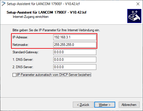
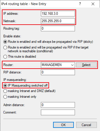
Die Angabe eines Standard-Gateways ist in diesem Fall nicht erforderlich, da kein Routing über diese Verbindung erfolgen soll.

Entering a Default gateway is not necessary in this case, as no routing is to be performed via this connection.

Image Added

  • In this step it is imperative that you select the option Leave the current default route (not recommended). Otherwise the Internet connection set up in step 2 won't be functional anymore!

Image Added


3.2) Manual configuration steps on the Gateway router

Image Removed

  • Wählen Sie in diesem Schritt unbedingt die Option Belassen der bisherigen Default-Route aus (nicht empfohlen). Die in Schritt 2. eingerichtete Internet-Verbindung ist ansonsten nicht mehr funktionsfähig!

Image Removed

3.2 Manuelle Konfigurations-Schritte auf dem Haupt-Gateway
:
3.2.1
Öffnen Sie die Konfiguration des Haupt-Gateways in LANconfig und wechseln in das Menü IP-
) Open the configuration of the Gateway router in LANconfig and go to the menu IP Router → Routing → IPv4
-Routing-Tabelle
routing table.
Image Removed
Image Added
3.2.2
Klicken Sie auf Hinzufügen, um einen neuen Routing-Eintrag zu erstellen.
) Click Add to create a new routing entry.
Image Added
Image Removed
3.2.3
Passen Sie die folgenden Parameter an
) Edit the following parameters:
  • IP
-Adresse: Geben Sie die Netz-Adresse des in Schritt
  • address: Enter the network address of the network entered in step 1.12
 bzw.
  • and 3.1
eingetragenen Netzwerks an
  • (in
diesem Beispiel die
  • this example 192.168.3.0).
Netzmaske: Tragen Sie die zugehörige Subnetzmaske ein (in diesem Beispiel die
  • Netmask: Enter the corresponding Subnet Mask (in this example 255.255.255.0)
  • Router:
Wählen Sie im Dropdownmenü die in Schritt 3.1 durch den Setup-Assistenten erstellte Internet-Gegenstelle aus (in diesem Beispiel
  • In the dropdownmenu select the Internet remote site created via the setup wizard in step 3.1 (in this example MANAGEMEN). 
  • IP
-Maskierung: Wählen Sie die Option IP-Maskierung abgeschaltet aus.
  • masquerading: Select the option IP Masquerading switched off.

Image Added

Image Removed

3.2.4) Write the configuration back to the device.
The
LANCOM modem
Modem router can now be reached and read out via the IP address 192.168.3.254.


Info

The sync status of the

xDSL

Modem router is also indicated by the xDSL-LED. When using the Bridge-Mode only the sync status is displayed. During active DSL sync the LED shines green permanently.