Versionen im Vergleich

Schlüssel

  • Diese Zeile wurde hinzugefügt.
  • Diese Zeile wurde entfernt.
  • Formatierung wurde geändert.
Seiteneigenschaften


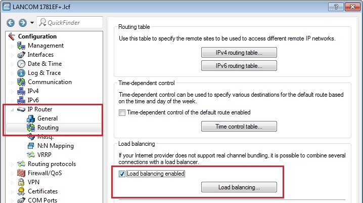
Description:

This document describes how to set up load balancing on LANCOM routers that do not have an integrated DSL modem.


Requirements:

You need the current version of LCOS and the current LANtools.
  • LCOS as of Version 8 (download)
  • LANtools as of Version 8.50 (download)
  • A LANCOM router without integrated DSL modem (e.g. a LANCOM 1781EF+)
  • One external xDSL modem for each Internet connection. Please refer to the technical specifications of your device to determine the number of Internet connections that your LANCOM router can manage.


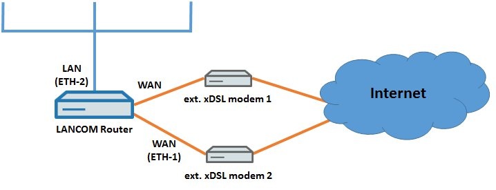
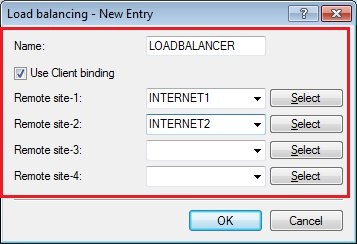
Scenario:

The configuration is carried out for the following example scenario.
  • Two DSL connections are to be load balanced so that they can both be used at the same time.
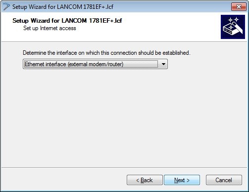
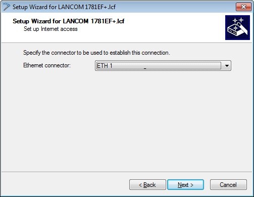
  • The first Internet connection is to be implemented with an external xDSL modem, which is connected to the LANCOM router's WAN port.
  • The second Internet connection is to be implemented with an additional external xDSL modem, which is connected to the Ethernet port LAN 1 on the LANCOM router.
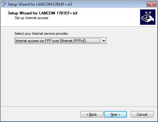
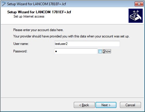
  • The LANCOM router handles the dial-in and logging on at the provider for both of the DSL connections.
  • The LANCOM router is already connected to the local network via Ethernet interface LAN 2.


Information:
The LANCOM 1781EF+ enables you to operate up to a maximum of four xDSL connections. For clarity, this example configuration is limited to two DSL lines.
Image Removed

Image Added


Setting up the first Internet connection:

1. Launch the Setup Wizard for the LANCOM router and select the option Set up Internet access.
Image Removed

Image Added

2. In this example we use the IPv4 internet protocol.
Image Removed

Image Added

3. Specify that the connection is to be established via the Ethernet interface.
Image Removed

Image Added

4. As the first external DSL modem is connected to the WAN port of the LANCOM router, the WAN Ethernet port must be selected in the following dialog.
Image Removed

Image Added

5. Select your country.
Image Removed

Image Added

6. Select the option Internet access via PPP over Ethernet.
Image Removed

Image Added

7. Enter a name for your Internet connection. In the interests of clarity we use the name INTERNET1 for this example.
Image Removed

Image Added

8. Enter your login data in the following dialog.
Image Removed

Image Added

9. Select the corresponding time model.
Image Removed

Image Added

10. You can apply the following default settings without modification. If you wish to use a different time for the daily forced disconnection, change the values in the appropriate fields.
Image Removed

Image Added

11. In this example, no backup connection is used, so we will retain the default settings.
Image Removed

Image Added

12. Exit the setup Internet connection wizard with the Finish button. The configured values are then written to the LANCOM router.
Image Removed

Image Added

13. After the configuration is written to the device, the setup wizard asks whether you want to continue one with another wizard.
At this point confirm this with yes, because another DSL connection has to be set up.


Setting up the second Internet connection:

1. Select the option Set up Internet access again.
Image Removed

Image Added

2. In this example we use the IPv4 internet protocol.
Image Removed

Image Added

3. Specify that the connection is to be established via the Ethernet interface.
Image Removed

Image Added

4. As the second external DSL modem is connected to the LAN1 port of the LANCOM router, the LAN1 Ethernet port must be selected in the following dialog.
Image Removed

Image Added

5. Select your country.
Image Removed

Image Added

6. Select the option Internet access via PPP over Ethernet.
Image Removed

Image Added

7. Enter a name for your Internet connection. At this point it is important to give this Internet connection a different name than the first one (INTERNET1). In the interests of clarity we use the name INTERNET2 for this example.
Image Removed

Image Added

8. Enter your login data in the following dialog.
Image Removed

Image Added

9. Select the corresponding time model:
Image Removed

Image Added

10. You can apply the following default settings without modification. If you wish to use a different time for the daily forced disconnection, change the values in the appropriate fields.
Image Removed

Image Added

11. In this example, no backup connection is used, so we will retain the default settings.
Image Removed

Image Added

12. A warning appears at this point because the previously established Internet connection INTERNET1 is configured as the default route.

For now, select the option leave the current default route. Later in the configuration, we will replace the DSL remote site of the default route with a load-balancing remote.
Image Removed

Image Added

13. Exit the setup Internet connection wizard with the Finish button. The configured values are then written to the LANCOM router.
Image Removed

Image Added

14. After the configuration is written to the device, the setup wizard asks whether you want to continue one with another wizard. Select No at this point, because the setup wizard is not required for the remaining steps in the configuration.


Manual configuration steps:

For the remainder of the configuration we have to continue in the configuration dialog for the LANCOM router.

1. Select the DSL-1 interface from the interface settings:
Image Removed

Image Added

2. In the fields downstream and upstream rate, enter the data transfer rates for the DSL line.
Image Removed

Image Added

3. Select the DSL-2 interface from the interface settings and enter the data for downstream and upstream rate.
Image Removed

Image Added


Configuring load balancing:

1. In order to configure the load balancing, switch to the menu item IP Router -> Routing -> Load balancing.

2. Next, activate load balancing.
Image Removed

Image Added

3. Then open the load-balancing table and define a virtual remote site named LOADBALANCER. You can use any name of your choice. When using a loadbalancer it is recommended to activate the Client binding function (available as of LCOS 9.10, also see
Image Removed
Image Added ).

4. Assign the two DSL remote sites INTERNET1 and INTERNET2 to the virtual remote site LOADBALANCER.
Image Removed

Image Added

5. Accept your entries with OK.

6. Exit the load balancing table and open the IPv4 routing table.
Image Removed

Image Added

7. Open the routing entry for the default route with a double click.
Image Removed

Image Added

8. Assign the load balancing device to the default route LOADBALANCER. Click on OK.
Image Removed

Image Added

9. The routing table should then appear as follows:
Image Removed

Image Added

10. Close the routing table and write the configuration back to the LANCOM router.

11. After writing the configuration to the device, the two Internet connections are established. This concludes the configuration.

Function check:

Proceed as follows to verify that everything is functioning as expected:

1. Start a SSH session on your LANCOM router (e.g. Putty).

2. Using the command line interface, enter the command trace # load and press Enter.

3. The trace output should appear as in the figure below.
Image Removed

Image Added

4. Stop the trace by entering the command trace # load again. Alternatively you can simply close the SSH client.

Information:
The load balancing mechanism reacts to the capacity utilization levels (number of sessions) of the Internet connections and distributes packets appropriately between the DSL remote sites.

With load balancing, the two DSL connections are not bundled.The load is merely distributed between the connections.