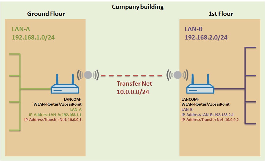
a company building, LAN-A with the address range 192.168.1.0/24is operated on the ground floor. LAN-B with the address range 192.168.2.0/24is operated one floor up.
These two networks are to be interconnected. Due to infrastructure reasons, no Ethernet cable can be laid, so the networks are to be interconnected via WLAN. For this purpose,
a
a LANCOM WLAN router or access pointis located in each local network.
The WLAN routers or access points are connected via a point-to-point link. Then
an
an intermediate network(here: Transfer Net) with the IP address range 10.0.0.0/24is configured between the devices.
Image Removed
Image Added
Procedure:
1) Configuring the point-to-point link:
1.1) Set up a point-to-point link between the LANCOM WLAN routers or access points. For a detailed description, see
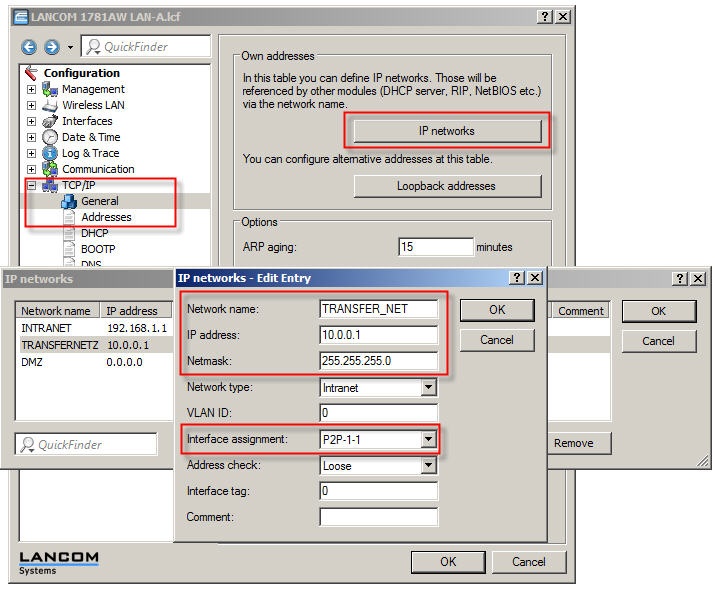
the configuration of the WLAN router/access point in LAN-A in LANconfigand go to the
menu Configuration ->
menu TCP/IP (or IPv4)
->
→ General
->
→ IP networks.
2.2) Click on the
button
button Add...to configure a new IP network:
In the Network namefield enter the name of TRANSFER_NET, for example.
In the IP address field, enter the IP address to be given to the LAN-A WLAN router/access point in the transfer/intermediate network. In this example, this is the IP address 10.0.0.1.
Set the netmaskto 255.255.255.0.
Set the Interface assignment field to the point-to-point interface P2P-1-1.
Image Removed
Image Added
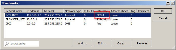
2.3) Open the configuration of
the
the INTRANET network and set the interface assignment to BRG-1.
Image Removed
Image Added
2.4) Open
the
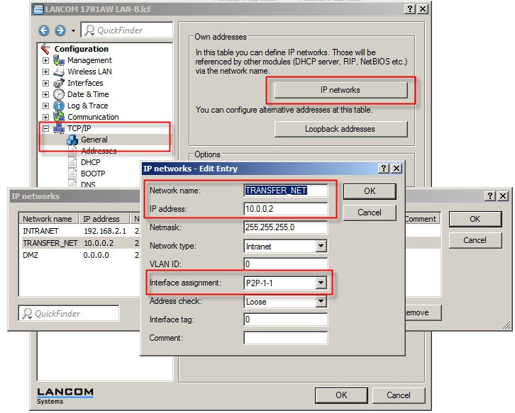
the configuration of the WLAN router/access point in LAN-Band go to the
menu Configuration ->
menu TCP/IP (or IPv4)
->
→ General
->
→ IP networks.
2.5) Click on the
button
button Add...to configure a new IP network:
In the Network namefield enter the name of TRANSFER_NET, for example.
In the IP address field, enter the in the intermediate (transfer) network IP addressto be given to the WLAN router/access point in LAN-B. In this example, this is the IP address 10.0.0.2.
Set the netmaskto 255.255.255.0.
Set the Interface assignment field to the point-to-point interface P2P-1-1.
Image Removed
Image Added
2.6) Open the configuration of
the
the INTRANET network and set the interface assignment to BRG-1.
Image Removed
Image Added
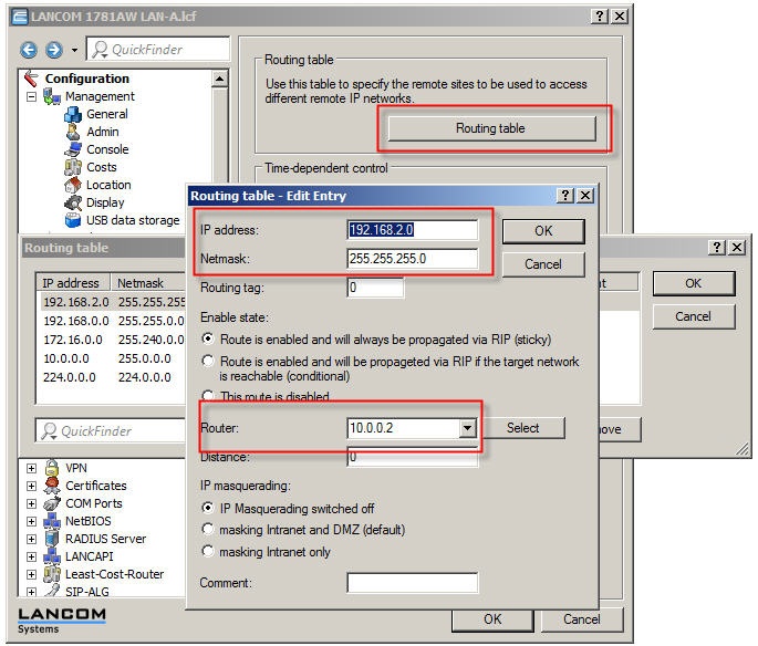
2.7) In
the
the routing tableof the LANCOM WLAN router/access point in LAN-A, a route must be configured to LAN-B.
In the IP addressfield, enter the network address of LAN-B. In this example, this is the IP address 192.168.2.0.
Set the netmaskto 255.255.255.0.
In the Router field, enter the intermediate (transfer) network IP address of the LANCOM WLAN router/access point in LAN-B.In this example, this is the IP address 10.0.0.2.
Image Removed
Image Added
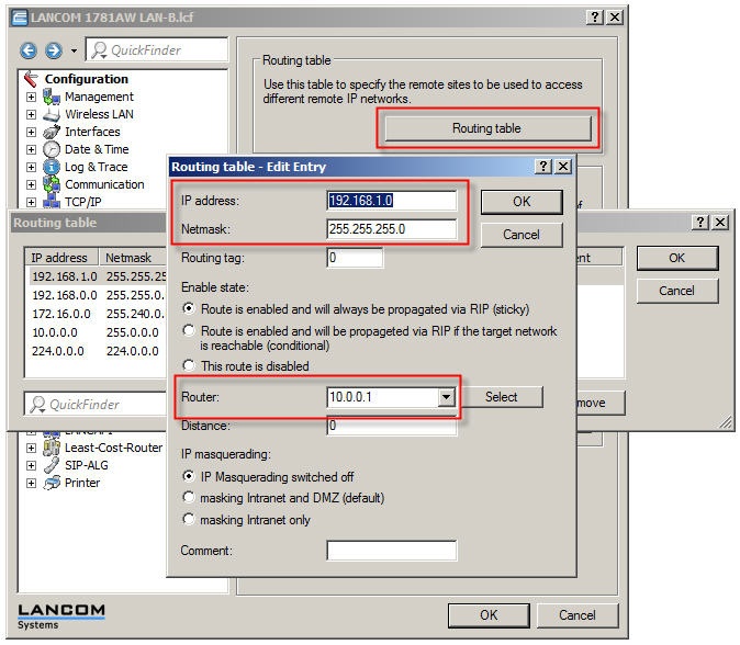
2.8) In
the
the routing tableof the LANCOM WLAN router/access point in LAN-B, a route must be configured to LAN-A.
In the IP addressfield, enter the network address of LAN-A. In this example, this is the IP address 192.168.1.0.
Set the netmaskto 255.255.255.0.
In the Router field, enter the intermediate (transfer) network IP address of the LANCOM WLAN router/access point in LAN-B.In this example, this is the IP address 10.0.0.1.
Image Removed
Image Added
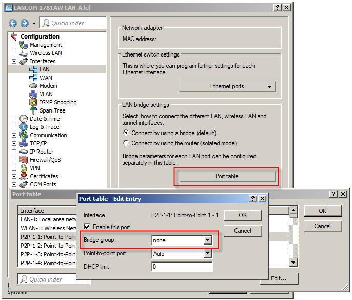
2.9) For
the
the WLAN router/access point on LAN-A and for the WLAN router/access point on LAN-B, open the
menu Configuration -> Interfaces -> LAN -> Port table ->
menu Interfaces → LAN → Port table → P2P-1-1.
2.10) Set the value in
the
the Bridge groupfield to none.
Image Removed
Image Added
2.11) Write the configuration back to
the
the WLAN router/access point on LAN-Aand the WLAN router/access point on LAN-Brespectively.