Description: This document describes how to configure a wireless network supported by multiple LANCOM access points, where guest users have to enter their user credentials at the central gateway in order to communicate with the Internet (Public Spot).
| Info |
|---|
The use of the device with active Public Spot as gateway and DNS server in the Public Spot network is mandatory! The management ports for HTTP (port 80) and HTTPS (port 443) must not be changed and have to be left on the default values! Please refer to this article in our Knowledge Base (see steps 1.8) - 1.9)). If the integrated SSL certificate is used, a warning is displayed when invoking an HTTPS website due to an unknown certificate! Please refer to this article in our Knowledge Base (see "Security notice for the SSL-HTTPS certificate"). |
Scenario: - After logging in to the Public Spot via the LAN and/or WLAN, guests should be able to communicate with the Internet.
- Employees should be able to use the LAN and/or WLAN to communicate with the Internet and intranet without having to login.
- No communication is allowed between
|
the networks GUEST and COMPANY- the guest and company networks.
|
 Image Removed
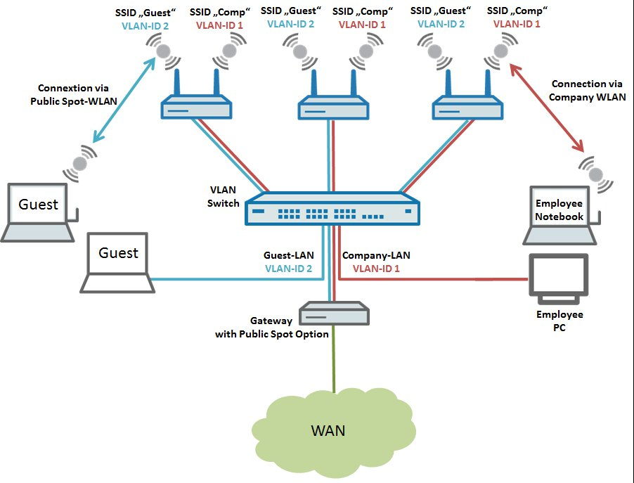 Image Added Image AddedThe following steps describe how to configure the central LANCOM gateway with its Public Spot option, and also the configuration of the LANCOM switch and a LANCOM access point. |
To operate more than one LANCOM access point, the steps taken for the configuration can be repeated for any number of APs. |
Vorgehensweise. Konfiguration der lokalen Netzwerke und der VLANs auf dem Gateway Router) Configuring the local networks and VLANs on the gateway router: 1.1 |
Öffnen Sie die Konfiguration des Gateways per LANconfig und wechseln in das Menü IPv4 → Allgemein → IP-Netzwerke) Open the configuration of the gateway router in LANconfig and go to the menu IPv4 → General → IP networks. 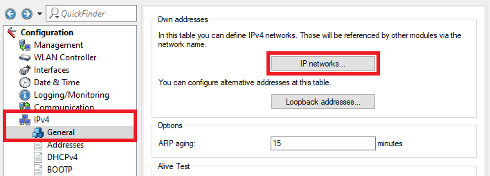 Image Modified Image Modified1.2 |
Klicken Sie im Dialog IP-Netzwerke auf die Schaltfläche Hinzufügen, um ein neues Netzwerk zu erstellen) In the IP networks dialog, click the Add button to create a new network. 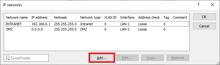 Image Modified Image Modified1.3 |
Passen Sie folgende Parameter für das Gast-Netz an:) Change the following parameters for the GUEST network: - Network name: Enter a descriptive name for the guest network (in this case GUEST
|
Netzwerkname: Vergeben Sie einen aussagekräftigen Namen für das Gast-Netzwerk (in diesem Fall GAST-AdresseGeben Sie eine IP-Adresse aus einem noch nicht verwendeten IP-Adressbereich an.- Enter an IP address from an IP address range which is not already in use.
- Netmask: Enter the subnet mask which is associated with the IP address
|
Netzmaske: Hinterlegen Sie die zu der IP-Adresse zugehörige Subnetzmaske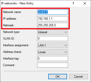 Image Modified Image Modified
1.4 |
Die Tabelle IP-Netzwerke muss anschließend wie folgt aussehen) The table IP networks has to appear as follows afterwards: 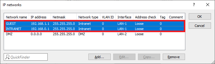 Image Modified Image Modified1.5 |
Wechseln Sie in das Menü ) Go to the menu IPv4 → DHCPv4 → DHCP |
-Netzwerkenetworks. 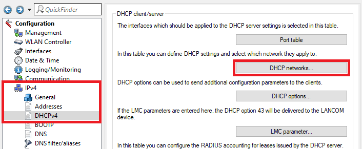 Image Modified Image Modified1.6 |
Klicken Sie auf Hinzufügen,um einen neuen Eintrag in der Tabelle DHCP-Netzwerke zu erstellen) Click Add to enter a new entry in the table DHCP networks. 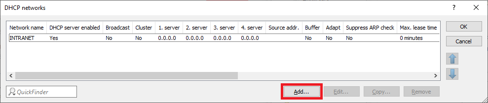 Image Modified Image Modified1.7 |
Passen Sie folgende Parameter anSchritt ) Edit the following parameters: |
Netzwerkname: Wählen Sie im Dropdownmenü das in - Network name: In the dropdown menu select the network created in step 1.3)
|
erstellte Netzwerk aus diesem Beispiel das Netzwerk GAST- this example the network GUEST).
- DHCP
|
-Server aktiviert: Wählen Sie im Dropdownmenü Ja aus, um den DHCP-Server zu aktivieren.- server enabled: In the dropdown menu select Yes to activate the DHCP server.
| Info |
|---|
If the address 0.0.0.0 is stored for each parameter in the configuration items Addresses for DHCP clients and Name server addresses, the router assigns its own IP address in this network as gateway and DNS server. Furthermore all free IP addresses within this network are used for assigning IP addresses. If necessary you can change the parameters. |
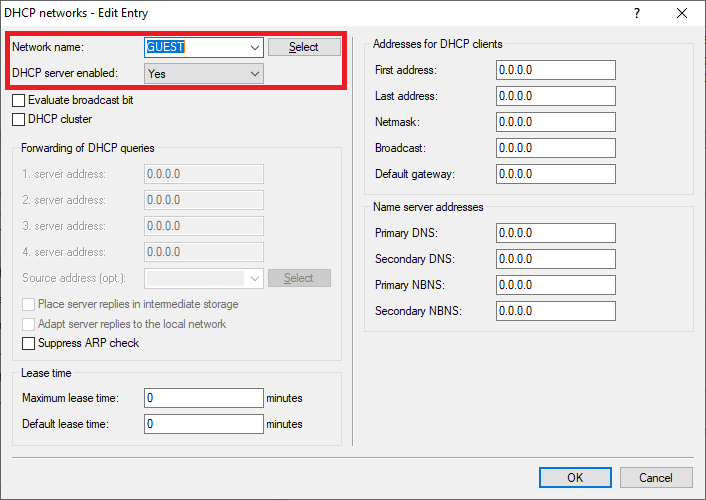 Image Added Image Added1.8) The table DHCP networks has to appear as follows afterwards: 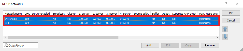 Image Added Image Added1.9) Go to the menu Interfaces → VLAN and activate the VLAN module. 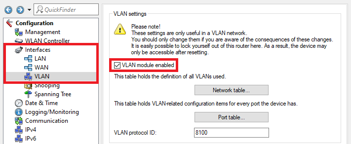 Image Added Image Added1.10) Go to the menu Network table. 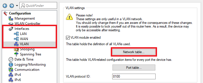 Image Added Image Added1.11) Select the entry Default_VLAN and click on the Edit button. 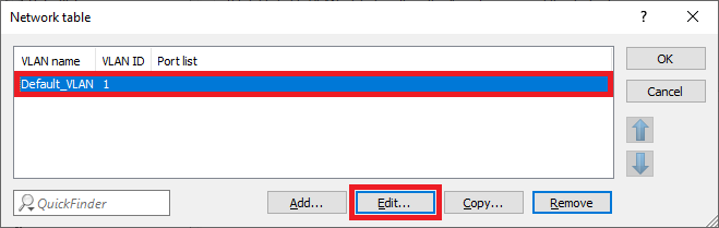 Image Added Image Added1.12) Click on the Select button next to Port list to select the interface LAN-1.
| Info |
|---|
The VLAN ID 1 is assigned to the company network. |
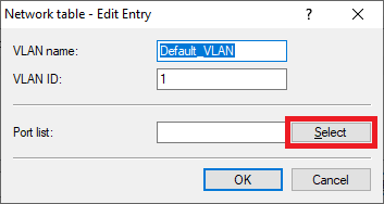 Image Added Image Added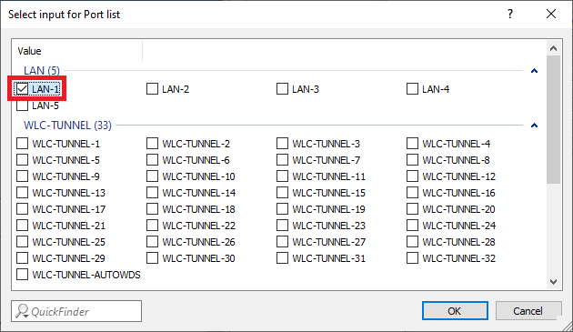 Image Added Image Added1.13) Create a new entry and change the following parameters: - VLAN name: Enter a descriptive name for the VLAN (in this example GUEST).
- VLAN ID: Enter the VLAN ID 2.
- Port list: Select the locial interface LAN-1.
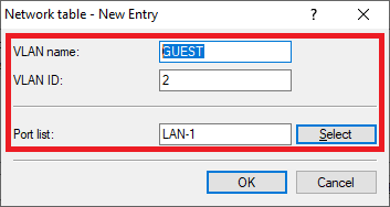 Image Added Image Added1.14) The Network table has to appear as follows afterwards: 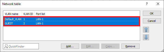 Image Added Image Added1.15) Go to the menu Port table. 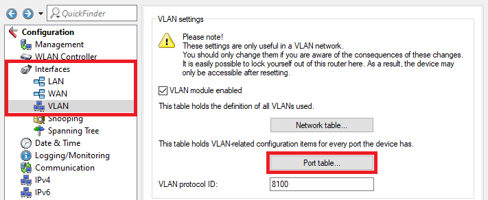 Image Added Image Added1.16) Select the VLAN port LAN-1: Local area network 1 and click Edit. 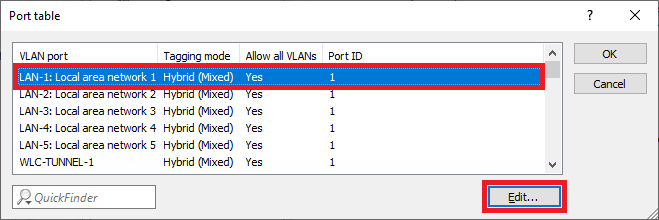 Image Added Image Added1.17) Change the following parameters: - VLAN tagging mode: Make sure that the tagging mode Hybrid (Mixed) is selected.
- Port VLAN ID: Make sure that the VLAN ID 1 is used.
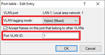 Image Added Image Added
1.18) Go to the menu IPv4 → General → IP networks to add the VLAN IDs to the networks. Image Added 1.19) Select the network INTRANET and click Edit. 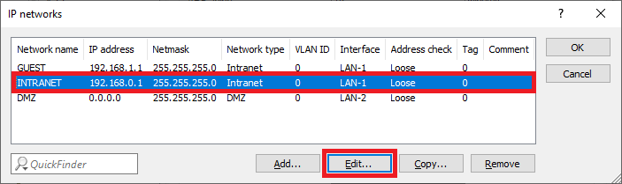 Image Added Image Added1.20) Enter the VLAN-ID 1 since it belongs to the company network (INTRANET). 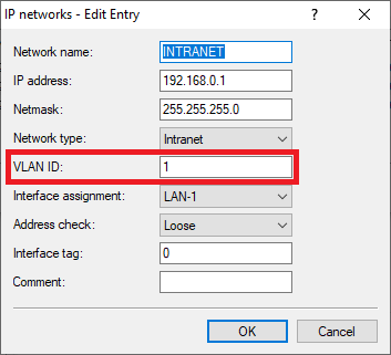 Image Added Image Added1.21) Edit the network GUEST and change the following parameters: - VLAN ID: Enter the VLAN ID 2.
- Interface tag: Enter an Interface tag unequal 0, so that the communication between the network GUEST and the network INTRANET is prevented (in this example the tag 1 is used).
| Info |
|---|
Networks that have been given an interface tag can only communicate with networks that share the same interface tag. This also means that the network INTRANET , which has the interface tag 0, is able to communicate with all networks , whatever interface tag they have. This makes it easier to access the guest network from the company network . It is not possible to communicate from the guest network to the company network . |
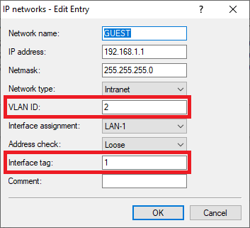 Image Added Image Added
1.22) The table IP networks has to appear as follows afterwards: 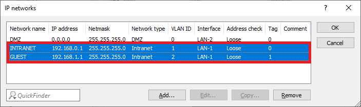 Image Added Image Added1.23) The network and VLAN configuration is complete. Write the configuration back into the router.
2) Configuring the Public Spot and the RADIUS server on the gateway router 2.1) Go to the menu Public-Spot → Authentication and select the mode Authenticate with name and password.  Image Added Image Added2.2) Go to the menu Public Spot → Server → Operational settings. 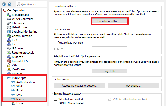 Image Added Image Added2.3) Go to the menu Interfaces. 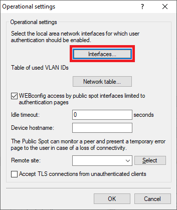 Image Added Image Added2.4) Select the Interface for the Public Spot authentication (in this example the interface LAN-1), and click Edit. 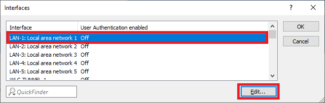 Image Added Image Added2.5) Activate the User Authentication for the interface LAN-1: Local area network 1. 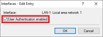 Image Added Image Added2.6) Go to the menu Network table to specify which VLAN ID should be used in conjunction with the Public Spot. 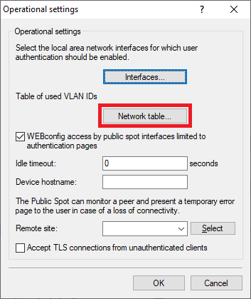 Image Added Image Added2.7) Click Add to create a new entry. 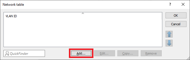 Image Added Image Added2.8) Select the VLAN ID 2. 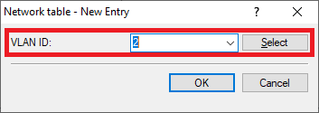 Image Added Image Added2.9) Go to the menu Public Spot → Users → RADIUS server to point to the integrated RADIUS server. 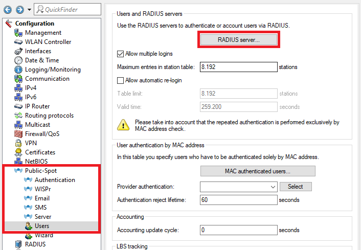 Image Added Image Added2.10) Ex factory there is an entry named LOCAL. It points to the integrated RADIUS and Accounting server.
| Info |
|---|
If the entry LOCAL doesn't exist, create an entry and enter any name. |
Make sure that the following parameters are used: |
| Info |
|---|
Ist bei Adressen für DHCP-Clients und Nameserver-Adressen bei den einzelnen Parametern die 0.0.0.0 hinterlegt, vergibt der Router seine eigene IP-Adresse in diesem Netzwerk als Gateway und DNS-Server und verwendet alle freien IP-Adressen in diesem Netzwerk für die Adressvergabe. Bei Bedarf können Sie die einzelnen Parameter anpassen. |
 Image Removed
1.8 Die Tabelle DHCP-Netzwerke muss anschließend wie folgt aussehen:
Image Removed 1.9 Wechseln Sie in das Menü Schnittstellen → VLAN und aktivieren das VLAN-Modul.
Image Removed 1.10 Wechseln Sie in das Menü VLAN-Tabelle.
 Image Removed
1.11 Markieren Sie den Eintrag Default_VLAN und klicken auf Bearbeiten.
Image Removed 1.12 Klicken Sie bei Port-Liste auf die Schaltfläche Wählen, um das Interface LAN-1 auszuwählen.
| Info |
|---|
Die VLAN-ID 1 wird dem Firmen-Netzwerk zugeordnet. |
 Image Removed
 Image Removed
1.13 Erstellen Sie ein einen neuen Eintrag und passen folgende Parameter an:
- VLAN-Name: Vergeben Sie einen aussagekräftigen Namen für das VLAN (in diesem Beispiel GAST).
- VLAN-ID: Hinterlegen Sie die VLAN-ID 2.
- Port-Liste: Fügen Sie die logische Schnittstelle LAN-1 hinzu.
Image Removed 1.14 Die VLAN-Tabelle muss anschließend wie folgt aussehen:
Image Removed 1.15 Wechseln Sie in das Menü Port-Tabelle.
Image Removed 1.16 Markieren Sie den VLAN-Port LAN-1: Lokales Netzwerk 1 und klicken auf Bearbeiten.
Image Removed 1.17 Passen Sie folgende Parameter an:
- VLAN-Tagging-Modus: Stellen Sie sicher, dass der Tagging-Modus Hybrid (Gemischt) ausgewählt ist.
- Port-VLAN-ID: Stellen Sie sicher, dass die VLAN-ID 1 hinterlegt ist.
Image Removed
1.18 Wechseln Sie in das Menü IPv4 → Allgemein → IP-Netzwerke, um in den Netzwerken die VLAN-IDs zu hinterlegen.
Image Removed 1.19 Markieren Sie das Netzwerk INTRANET und klicken auf Bearbeiten.
Image Removed 1.20 Setzen Sie die zum Netzwerk gehörende VLAN-ID auf den Wert 1.
Image Removed 1.21 Bearbeiten Sie das Netzwerk GAST und passen folgende Parameter an:
- VLAN-ID: Hinterlegen Sie die VLAN-ID 2.
- Schnittstellen-Tag: Hinterlegen Sie ein Schnittstellen-Tag ungleich 0, damit die Kommunikation zwischen dem Netzwerk GAST und dem Netzwerk INTRANET unterbunden wird (in diesem Beispiel wird das Tag 1 verwendet).
| Info |
|---|
Netzwerke, welche über ein Schnittstellen-Tag verfügen, können nur mit Netzwerken kommunizieren, die über das gleiche Schnittstellen-Tag verfügen. Außerdem bedeutet dies, dass das Netzwerk INTRANET, welches über das Schnittstellen-Tag 0 verfügt, mit allen Netzwerken mit beliebigem Schnittstellen-Tag kommunizieren kann. Dies dient dem einfacheren Zugriff vom INTRANET-Netzwerk auf das GAST-Netzwerk. Eine Kommunikation vom GAST-Netzwerk in das INTRANET-Netzwerk ist nicht möglich. |
Image Removed
1.22 Die Tabelle IP-Netzwerke muss anschließend wie folgt aussehen:
Image Removed 1.23 Die Netzwerk- und VLAN-Konfiguration ist damit abgeschlossen. Schreiben Sie die Konfiguration in den Router zurück.
2. Konfiguration des Public-Spot und des RADIUS-Servers auf dem Gateway Router:
2.1 Wechseln Sie in das Menü Public-Spot → Anmeldungund setzen den Anmeldungs-Modus auf Anmeldung mit Name und Passwort.Image Removed 2.2 Wechseln Sie in das Menü Public Spot → Server → Betriebseinstellungen.
Image Removed 2.3 Wechseln Sie in das Menü Interfaces.
Image Removed 2.4 Markieren Sie das Interface, über die die Authentifizierung am Public Spot erfolgen soll (in diesem Beispiel das Interface LAN-1), und klicken auf Bearbeiten.
Image Removed 2.5 Aktivieren Sie die Benutzer-Anmeldung für das Interface LAN-1: Lokales Netzwerk 1.
Image Removed 2.6 Wechseln Sie in das Menü VLAN-Tabelle, um festzulegen, welche VLAN-ID in Verbindung mit dem Public-Spot verwendet werden soll.Image Removed 2.7 Erstellen Sie einen neuen Eintrag, indem Sie auf Hinzufügen klicken.
Image Removed 2.8 Tragen Sie in das Feld VLAN-ID die VLAN-ID 2 ein und bestätigen Sie mit OK.
Image Removed 2.9 Wechseln Sie in das Menü Public Spot → Benutzer → RADIUS-Server, um einen Verweis auf den integrierten RADIUS-Server zu hinterlegen.
Image Removed 2.10 Ab Werk ist bereits ein Eintrag namens LOCAL vorhanden. Dieser verweist auf den integrierten RADIUS- und Accounting-Server.
| Info |
|---|
Sollte noch kein Eintrag vorhanden sein, legen Sie diesen an und vergeben einen beliebigen Namen. |
Stellen Sie sicher, dass die Parameter wie folgt gesetzt sind:
Auth.-Server Adresse-Server Port-Server Adresse- server address: 127.0.0.1
- Acc.
|
-Server PortImage Removed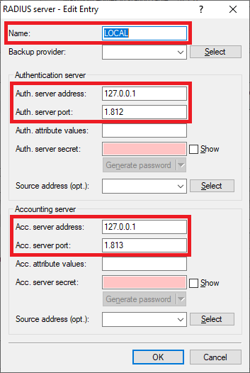 Image Added Image Added
2.11 |
Wechseln Sie in das Menü ) Go to the menu Public Spot → |
Assistent → Wizard → Public Spot SSIDs. |
Image Removed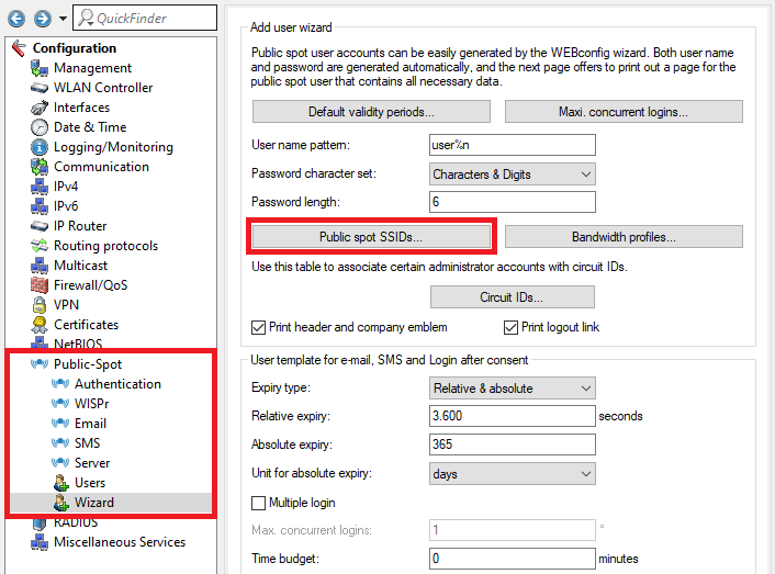 Image Added Image Added2.12 |
Erstellen Sie einen neuen Eintrag und passen folgende Parameter an) Create a new entry and change the following parameters: |
Hinterlegen Sie die in Schritt - Enter the SSID for the guest network created in step 4.4
|
erstellte SSID diesem Beispiel GAST), um den Namen der SSID für den Public-Spot-Zugang auf die Voucher für die Public Spot Benutzer zu drucken.SSID selektiert: Setzen Sie diese Option auf Ja, damit die SSID immer bei Durchlaufen des Setup-Assistenten Public-Spot-Benutzer erstellen auf den Voucher gedruckt wird.Image Removed
2.13 Wechseln Sie in das Menü RADIUS → Server und aktivieren die Funktionen RADIUS-Authentisierung und RADIUS-Accounting.
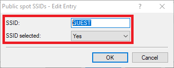 Image Removed
2.14 Wechseln Sie in das Menü RADIUS-Dienste Ports.
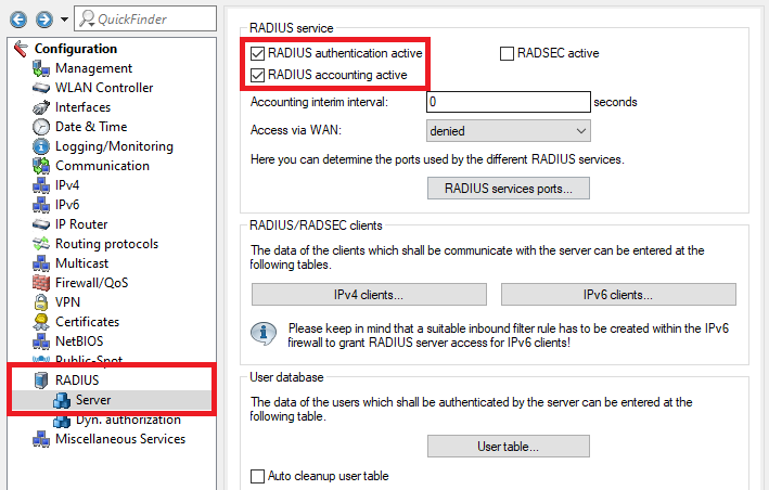 Image Removed
2.15 Stellen Sie sicher, dass bei Authentifizierungs-Port der Port 1812 und bei Accounting-Port der Port 1813 hinterlegt ist.
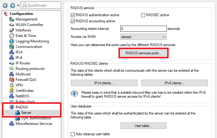 Image Removed
2.16 Die Konfiguration des Public Spot und des RADIUS-Servers ist damit abgeschlossen. Schreiben Sie die Konfiguration in den Router zurück.
3. VLAN-Konfiguration auf dem LANCOM Switch:
3.1 Öffnen Sie die Konfiguration des LANCOM Switch in einem Web-Browser und wechseln Sie in das Menü - this example Guest), to print the name of the SSID on the Public Spot voucher.
- SSID selected: Set this option to Yes, in order for the SSID to be printed on the Public Spot voucher whenever a Public Spot user is created and the voucher printed via the setup wizard Create Public Spot Account.
Image Added 2.13) Go to the menu RADIUS → Server and activate the functions RADIUS authentication and RADIUS accounting. Image Added 2.14) Go to the menu RADIUS services ports. Image Added 2.15) Make sure that the Authentication port is set to 1812 and the Accounting port to 1813. 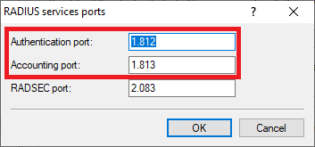 Image Added Image Added2.16) The configuration of the Public Spot and the RADIUS server is complete. Write the configuration back into the router.
3) Configuring the VLAN on the LANCOM switch: 3.1) Open the configuration of the LANCOM switch in a web browser and go to the menu Configuration → VLAN → VLAN Membership. 3.2 |
. In diesem Konfigurationsbeispiel sollen die Switch Ports folgendermaßen belegt sein) In this example the switch ports should be configured as follows: |
am Gateway Router am - gateway router at Port 3
- Port 23
|
wird für den kabelgebundenen LAN-Zugang zum Netzwerk FIRMA - is used for access to the company network (192.168.0.0/24)
|
verwendet 24 wird für den kabelgebundenen LAN-Zugang zum Netzwerk GAST - 24 is used for access to the guest network (192.168.1.0/24)
|
verwendet. Der Zugang wird per - via LAN. The authentication is controlled via the Public Spot
|
geregelt Tragen Sie im bereits existierenden Default-VLAN den Namen des Netzwerkes FIRMA ein) Edit the existing Default VLAN and enter the name of the network (in this example COMPANY). 3.4 |
Erstellen Sie ein neues VLAN mit der Schaltfläche Add New VLAN. Vergeben Sie die VLAN-ID 2 und tragen Sie als Namen GAST ein.3.5 Setzen Sie bei dem Netzwerk GAST jeweils einen Haken bei Port 1, Port 3 und Port 24.
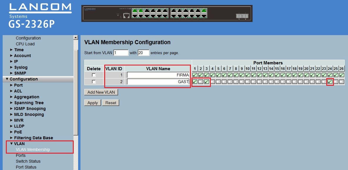 Image Removed
) Add a new VLAN via the button Add New VLAN. Enter the name of the network (in this example GUEST) and enter the VLAN ID 2. 3.5) Tick the checkboxes with the Ports 1, 3 and 24 for the VLAN GUEST. 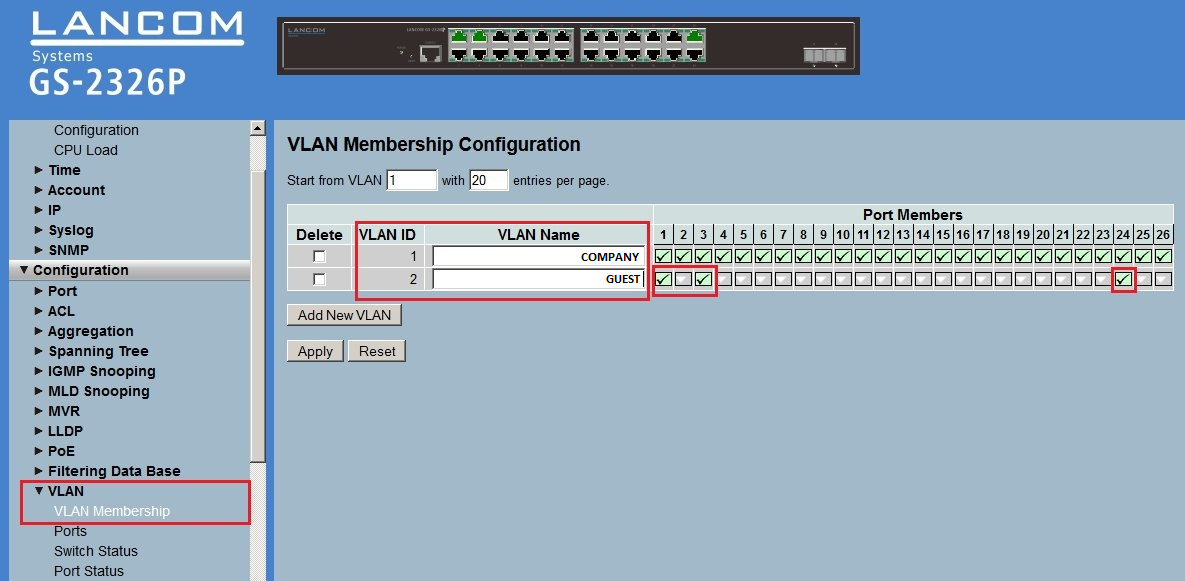 Image Added Image Added3.6) Go to the menu Ports and edit the port configuration for the ports |
Ports und vorStellen Sie sicher, dass bei den Ports 1 und 3 als Egress Rule der Wert Hybrid und als PVID der Wert 1 hinterlegt ist- Make sure, that the Egress Rule is set to Hybrid for the Ports 1 and 3 and that the PVID is set to 1.
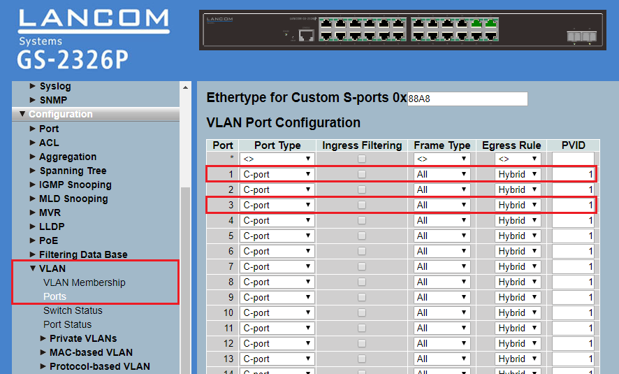 Image Modified Image Modified |
Setzen Sie bei die Setzen Sie bei Port 24 die Egress Rule auf den Wert Access und hinterlegen im Feld PVID die VLAN-ID auf den Wert Access und stellen sicher, dass bei PVID der Wert 1 hinterlegt ist.- to Access and make sure, that the PVID is set to 1.
- For the Port 24 set the Egress Rule to Access and make sure, that the PVID is set to
|
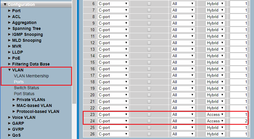 Image Modified Image Modified3.7 |
. Die VLAN-Konfiguration auf dem LANCOM Switch ist damit abgeschlossen. Schreiben Sie die Konfiguration in das Gerät zurück.4. Konfiguration eines LANCOM Access Point:4.1 Wechseln Sie in das Menü IPv4 → Allgemein → IP-Netzwerke.
 Image Removed
) The VLAN configuration of the switch is complete. Write the configuration back into the device.
4) Configuring a LANCOM access point 4.1) Go to the menu IPv4 → General → IP networks. 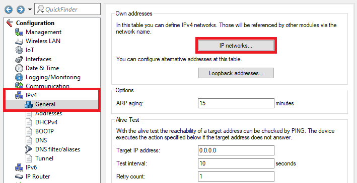 Image Added Image Added4.2) Assign an IP address from the company network to the Access Point (in this example the network 192.168.0.0/24) |
und hinterlegen die VLAN-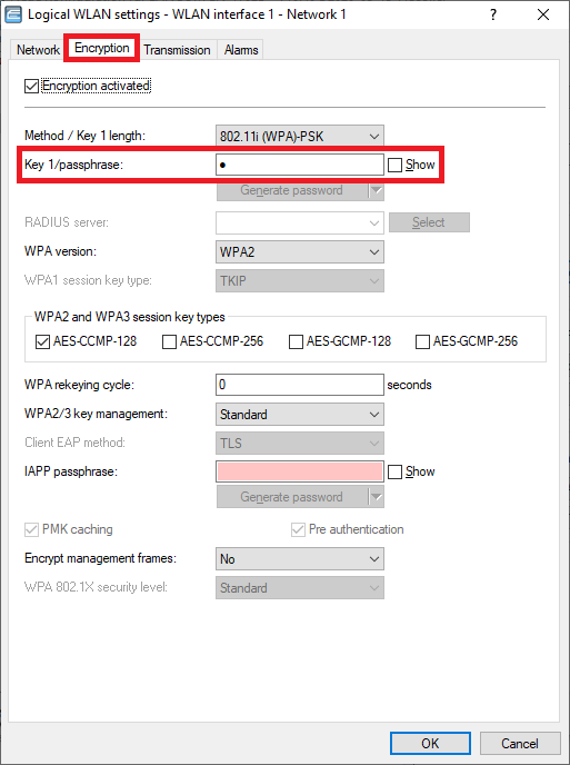 Image Removed
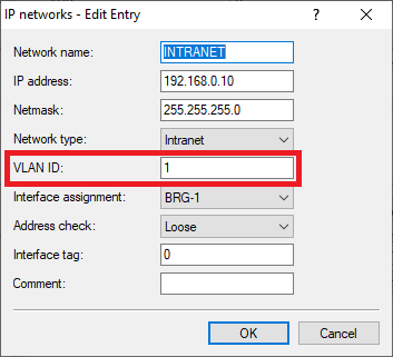 Image Added Image Added4.3 |
Wechseln Sie in das Menü ) Go to the menu Wireless-LAN → |
Allgemein → Logische WLAN-EinstellungenGeneral → Logical WLAN settings. |
 Image Removed
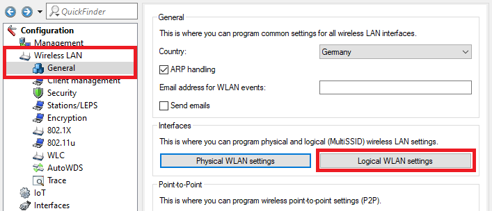 Image Added Image Added4. |
4 Erstellen Sie für jedes WLAN-Modul jeweils ein WLAN mit der SSID FIRMA und GAST und passen die Verschlüsselungs-Einstellungen an.4) Create a WLAN for the company network and the guest network for each radio module and edit the encryption parameters. WLAN interface 1 - Network 1: Network tab: - Make sure, that the checkbox WLAN network enabled is ticked.
- Enter a descriptive name for the SSID (in this example the name Comp).
Encryption tab: - Enter a WPA key for Key 1/passphrase. It has to be entered in WLAN devices to be able to connect to the WLAN.
Image Added Image Added
WLAN interface 1 - Network 2: Network tab: - Make sure, that the checkbox WLAN network enabled is ticked.
- Enter a descriptive name for the SSID (in this example the name Guest).
Encryption tab: - Deactivate the encryption. WLAN devices should authenticate themselves at the Public Spot via login credentials.
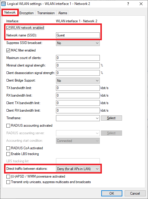 Image Added Image Added  Image Added Image Added
|
WLAN-Interface 1 - Netzwerk 1:
Reiter Netzwerk:
- Stellen Sie sicher, dass der Haken bei WLAN-Netzwerk aktiviert gesetzt ist.
- Vergeben Sie einen aussagekräftigen Netzwerk-Namen für die SSID (in diesem Beispiel der Name FIRMA).
Reiter Verschlüsselung:
- Hinterlegen Sie bei Schlüssel 1/Passphrase einen WPA-Key, der in den WLAN-Geräten eingegeben werden muss, damit diese sich im WLAN einbuchen können.
 Image Removed
  Image Removed
WLAN-Interface 1 - Netzwerk 2:
Reiter Netzwerk:
- Stellen Sie sicher, dass der Haken bei WLAN-Netzwerk aktiviert gesetzt ist.
- Vergeben Sie einen aussagekräftigen Netzwerk-Namen für die SSID (in diesem Beispiel der Name GAST).
Reiter Verschlüsselung:
- Deaktivieren Sie die Verschlüsselung. WLAN-Geräte sollen sich am Public Spot nur über die Zugangs-Daten authentifizieren.
 Image Removed
  Image Removed
WLAN-Interface 2 - Netzwerk 1: |
Reiter Netzwerk- Stellen Sie sicher, dass der Haken bei WLAN-Netzwerk aktiviert gesetzt ist.
- Vergeben Sie einen aussagekräftigen Netzwerk-Namen für die SSID (in diesem Beispiel der Name FIRMA).
Reiter Verschlüsselung:
- Hinterlegen Sie bei Schlüssel 1/Passphrase den WPA-Key, den Sie bereits für die Schnittstelle WLAN-Interface 1 - Netzwerk 1 vergeben haben.
 Image Removed
  Image Removed
- Make sure, that the checkbox WLAN network enabled is ticked.
- Enter a descriptive name for the SSID (in this example the name Comp).
Encryption tab: - Enter the same WPA key for Key 1/passphrase you used for the interface WLAN interface 1 - Network 1.
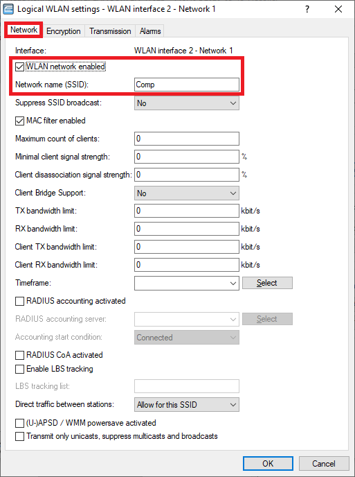 Image Added Image Added 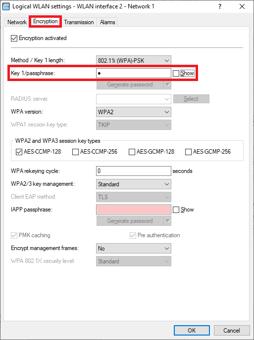 Image Added Image Added
WLAN interface 2 - Netzwerk 2: |
Reiter Netzwerk- Stellen Sie sicher, dass der Haken bei WLAN-Netzwerk aktiviert gesetzt ist.
- Vergeben Sie einen aussagekräftigen Netzwerk-Namen für die SSID (in diesem Beispiel der Name GAST).
Reiter Verschlüsselung:
- Deaktivieren Sie die Verschlüsselung. WLAN-Geräte sollen sich am Public Spot nur über die Zugangs-Daten authentifizieren.
 Image Removed
  Image Removed
4.5 Wechseln Sie in das Menü Schnittstellen → VLAN und aktivieren das VLAN-Modul.
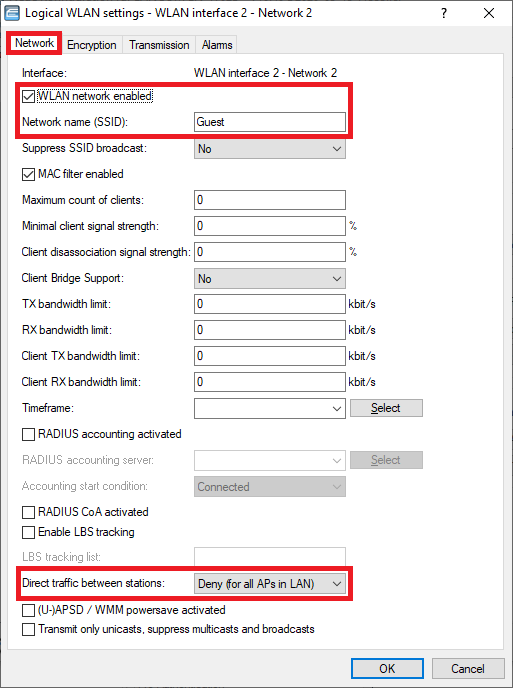 Image Removed
4.6 Wechseln Sie in das Menü VLAN-Tabelle.
 Image Removed
4.7 Markieren Sie den Eintrag Default_VLAN und klicken auf Bearbeiten.
 Image Removed
4.8 Klicken Sie bei Port-Liste auf Wählen, um die logischen Schnittstellen für das Firmen-Netzwerk hinzuzufügen.
| Info |
|---|
Ist bei Port-Liste die Wildcard *-* für alle logischen Schnittstellen hinterlegt, ist es empfehlenswert diese zu löschen und stattdessen die tatsächlich verwendeten Ports zu hinterlegen. |
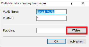 Image Removed4.9 Wählen Sie alle logischen Schnittstellen aus, über die das Firmen-Netzwerk kommunizieren soll (in diesem Beispiel die Schnittstellen
 - Make sure, that the checkbox WLAN network enabled is ticked.
- Enter a descriptive name for the SSID (in this example the name Guest).
Encryption tab: - Deactivate the encryption. WLAN devices should authenticate themselves at the Public Spot via login credentials.
Image Added 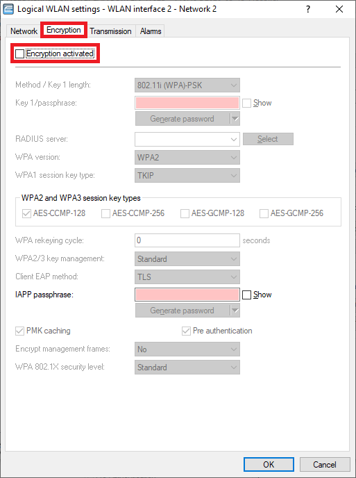 Image Added Image Added 4.5) Go to the menu Interfaces → VLAN and activate the VLAN module. 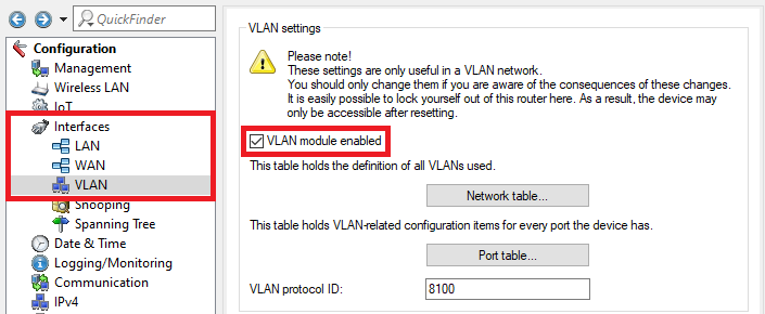 Image Added Image Added4.6) Go to the menu Network table. 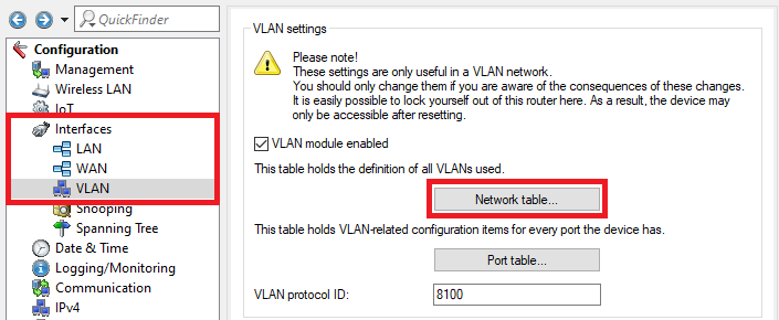 Image Added Image Added4.7) Select the entry Default_VLAN and click Edit. 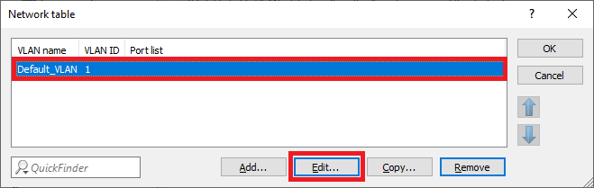 Image Added Image Added4.8) In the Port list click Select to add the logical interfaces for the company network.
| Info |
|---|
If the Port list contains the wildcard *-* which stands for all logical interfaces, it is recommended to delete it and enter the interfaces which are used instead. |
 Image Added Image Added4.9) Select all logical interfaces, which should communicate via the company network (in this example the interfaces |
und  Image Removed
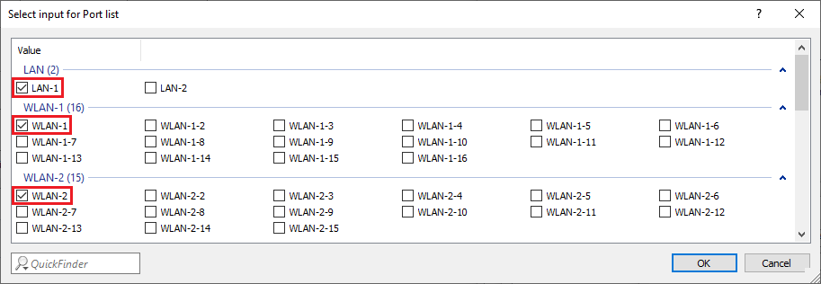 Image Added Image Added4.10 |
Erstellen Sie einen weiteren Eintrag und passen folgende Parameter an) Create a new entry and enter the following parameters: |
-Name: Vergeben Sie einen aussagekräftigen Namen für das VLAN (in diesem Beispiel GAST- name: Enter a descriptive name for this VLAN (in this example GUEST).
- VLAN
|
- Hinterlegen Sie die -Klicken Sie anschließend bei Port-Liste auf Wählen, um die logischen Schnittstellen für das Gast-Netzwerk hinzuzufügen.  Image Removed
4.11 Wählen Sie alle logischen Schnittstellen aus, über die das Gast-Netzwerk kommunizieren soll (in diesem Beispiel die Schnittstellen - Afterwards click on Select in the Port list to add the logical interfaces for the guest network .
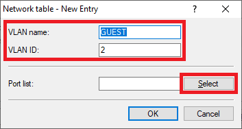 Image Added Image Added
4.11) Select all logical interfaces, which should communicate via the guest network (in this example the interfaces LAN-1, WLAN-1-2 |
und  Image Removed
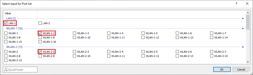 Image Added Image Added
4.12 |
Die VLAN-Tabelle muss anschließend wie folgt aussehen:) The Network table has to appear as follows afterwards: 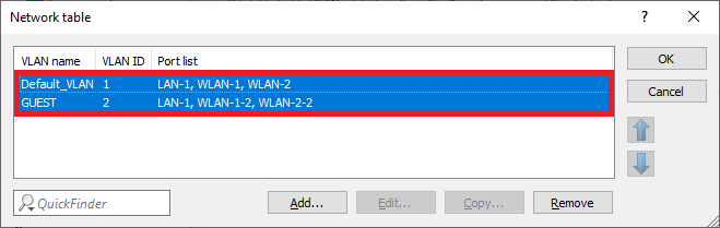 Image Added Image Added |
Image Removed Wechseln Sie in das Menü Port-Tabelle.Image Removed 4.14 Passen Sie die einzelnen logischen Schnittstellen wie folgt an) Go to the menu Port table. 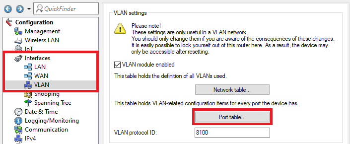 Image Added Image Added4.14) Edit the individual logical interfaces as follows: LAN-1: |
-Tagging-Modus: Stellen Sie sicher, dass der Tagging-Modus Hybrid (Gemischt) hinterlegt ist- tagging mode: Make sure, that the tagging mode Hybrid (Mixed) is used.
- Port
|
-- Stellen Sie sicher, dass die Port-VLAN-ID 1 hinterlegt ist- Make sure, that the Port VLAN ID 1 is used.
|
 Image Removed
 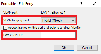 Image Added Image Added WLAN-1: |
-Tagging-Modus: Wählen Sie im Dropdownmenü den Tagging-Modus Access (Niemals) aus- tagging mode: In the dropdown menu select the tagging mode Access (Never).
- Port
|
-- Stellen Sie sicher, dass die Port-VLAN-ID 1 hinterlegt ist- Make sure, that the Port VLAN ID 1 is used.
WLAN-2: |
-Tagging-Modus: Wählen Sie im Dropdownmenü den Tagging-Modus Access (Niemals) aus- tagging mode: In the dropdown menu select the tagging mode Access (Never).
- Port
|
-- Stellen Sie sicher, dass die Port-VLAN-ID 1 hinterlegt ist- Make sure, that the Port VLAN ID 1 is used.
|
 Image Removed
 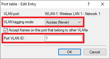 Image Added Image Added |
 Image Removed
  Image Added Image Added WLAN-1-2: |
VLAN-Tagging-Modus: Wählen Sie im Dropdownmenü den Tagging-Modus Access (Niemals) aus- VLAN tagging mode: In the dropdown menu select the tagging mode Access (Never).
- Port
|
-- Hinterlegen Sie die ---Tagging-Modus: Wählen Sie im Dropdownmenü den Tagging-Modus Access (Niemals) aus- tagging mode: In the dropdown menu select the tagging mode Access (Never).
- Port
|
-- Hinterlegen Sie die -- Image Removed
 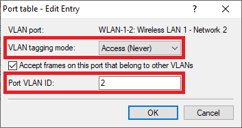 Image Added Image Added |
 Image Removed
 Image Added Image Added
4.15 |
Die Port-Tabelle muss anschließend wie folgt aussehen:) The Port table has to appear as follows afterwards: 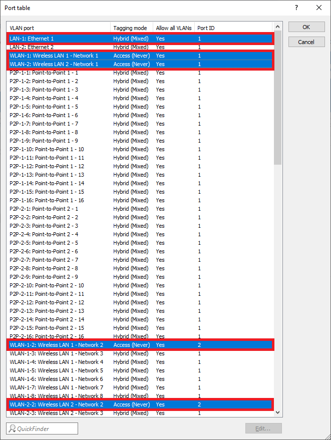 Image Added Image Added4.16) The configuration of the access point is complete. Write the configuration back into the device.
5) Configuring a further administrator for adding and managing Public Spot users: 5.1) Open the configuration of the gateway router in LANconfig and go to the menu Management → Admin → Further administrators. 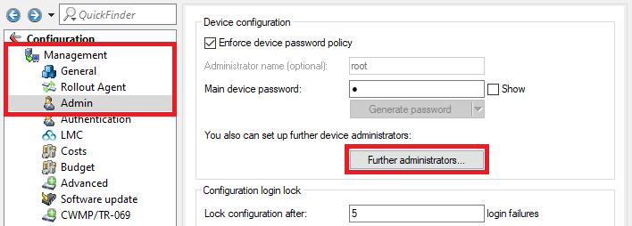 Image Added Image Added5.2) Create a further administrator and edit the following parameters: - Administrator: Enter a descriptive name for the further administrator.
- Password: Enter a password for the administrator.
- Access rights: Select None in the dropdown menu.
- Deactivate all Function rights except Public spot wizard (add user) and Public spot wizard (manage user), so that the further administrator is able to add and manage Public Spot users.
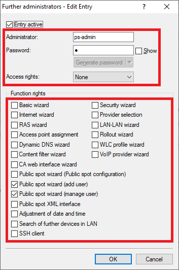 Image Added Image Added
5.3) The configuration of the further administrator is complete. Write the configuration back into the device.
6) Adding and managing Public Spot users in WEBconfig: 6.1) Invoke the IP address of the gateway router in a web browser and login with the login credentials of the further administrator (see step 5.2)). 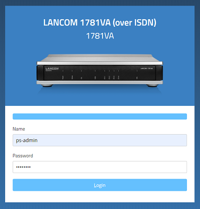 Image Added Image Added 6.2) It is possible to carry out the following actions in the menu Create Public Spot Account: - Create one or several Public Spot users by clicking on the button Create and Print.
- Create one or several Public Spot users by clicking on the button Create and CSV-Expor. Additionally the user data will be exported into a CSV file so that it can be processed further.
- By clicking on the button User Management you can invoke the menu Manage Public Spot Account.
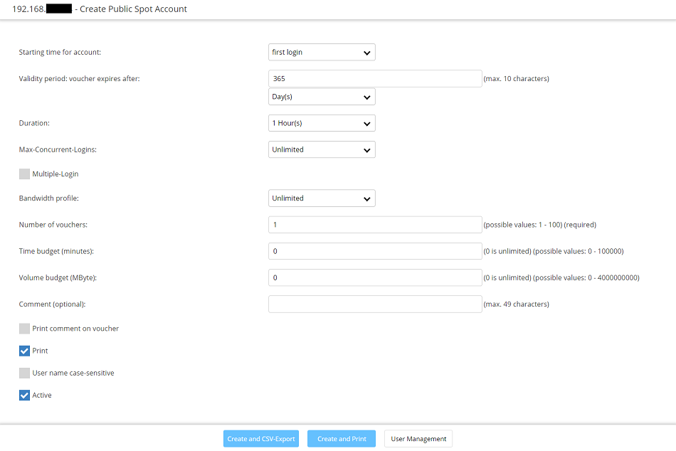 Image Added Image Added
6.3) It is possible to carry out the following actions in the menu Manage Public Spot Account: - The button Show/Hide column allows to mask individual columns. In the default setting all columns are displayed.
- By clicking Save as CSV a CSV file can be saved which contains all Public Spot users in the database.
- It is possible to change individual parameters (e.g. the Password or Expiry-Type) and save them.
- By clicking the button Delete you can delete individual users.
- By clicking on the button Print you can print vouchers for Public Spot users after creating them.
- By clicking on the button Add user you can invoke the menu Create Public Spot Account
|
Image Removed 4.16 Die Konfiguration des Access Points ist damit abgeschlossen. Schreiben Sie die Konfiguration in das Gerät zurück.
5. Einrichtung eines weiteren Administrators zur Einrichtung und Verwaltung von Public Spot Benutzern:
5.1 Öffnen Sie die Konfiguration des Gateway-Routers in LANconfig und wechseln in das Menü Management → Admin → Weitere Administratoren.
Image Removed 5.2 Erstellen Sie einen weiteren Administrator und passen folgende Parameter an:
- Administrator: Vergeben Sie einen aussagekräftigen Namen für den weiteren Administrator.
- Passwort: Hinterlegen Sie ein Passwort. mit dem sich der Administrator in WEBconfig anmelden kann.
- Zugriffs-Rechte: Wählen Sie im Dropdownmenü Keine aus.
- Deaktivieren Sie alle Funktions-Rechte bis auf Public-Spot-Assistent (Benutzer anlegen) und Public-Spot-Assistent (Benutzer verwalten), damit der Administrator Public Spot Benutzer anlegen und verwalten kann.
Image Removed
5.3 Die Konfiguration des weiteren Administrators ist damit abgeschlossen. Schreiben Sie die Konfiguration in den Router zurück.
6. Einrichtung und Verwaltung eines Public Spot Benutzers in WEBconfig:
6.1 Rufen Sie die IP-Adresse des Gateway-Routers in in einem Browser auf und loggen sich mit den Login-Daten des weiteren Administrators ein (siehe Schritt 5.2).
Image Removed 6.2 In dem Menü Public-Spot-Benutzer einrichten können Sie folgende Aktionen vornehmen:
- Erstellen Sie einen oder mehrere neue Public Spot Benutzer, indem Sie auf die Schaltfläche Anlegen und Drucken klicken.
- Erstellen Sie einen oder mehrere neue Public Spot Benutzer, indem Sie auf die Schaltfläche Anlegen und CSV-Export klicken. Zusätzlich werden die Benutzer-Daten in eine CSV-Datei exportiert, damit diese anschließend weiter bearbeitet werden können.
- Mit einem Klick auf die Schaltfläche Benutzerverwaltung aufrufen gelangen Sie in das Menü Public-Spot-Benutzer verwalten.
Image Removed
6.3 In dem Menü Public-Spot-Benutzer verwalten können Sie folgende Aktionen vornehmen:
Unter Spalte zeigen/verstecken können Sie einzelne Spalten ausblenden. Im Standard werden alle Spalten angezeigt.Mit einem Klick auf Als CSV speichern wird eine CSV-Datei mit allen aktuell angelegten Benutzern abgespeichert.Einzelne Parameter wie z.B. das Passwort oder der Ablauf-Typ können abgeändert und dann gespeichert werden.Mit einem Klick auf Löschen können einzelne Benutzer gelöscht werden.Mit einem Klick auf die Schaltfläche Benutzer anlegen gelangen Sie in das Menü Public-Spot-Benutzer einrichten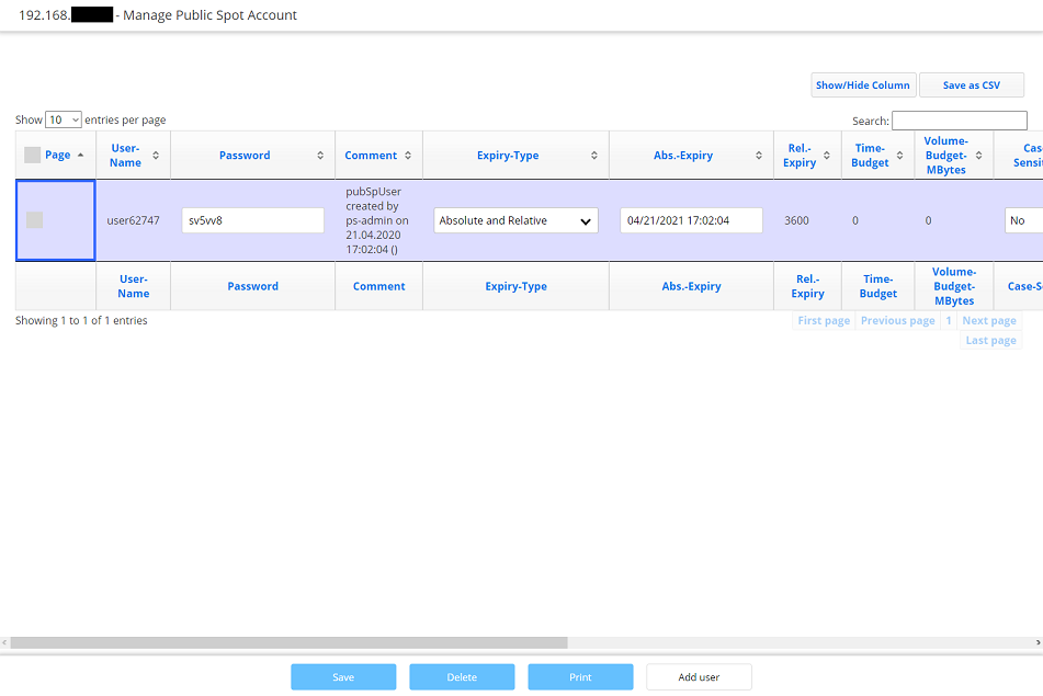 Image Modified Image Modified
|
