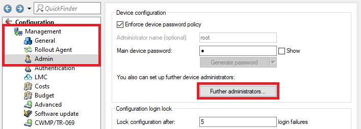
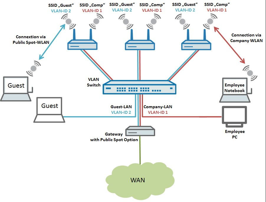
 Image Added Image AddedThe following steps describe how to configure the central LANCOM gateway with its Public Spot option, and also the configuration of the LANCOM switch and a LANCOM access point. To operate more than one LANCOM access point, the steps taken for the configuration can be repeated for any number of APs.
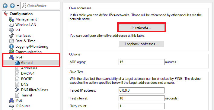
Procedure: 1) Configuring the local networks and VLANs on the gateway router: 1.1) Open the configuration of the gateway router in LANconfig and go to the menu IPv4 → General → IP networks. 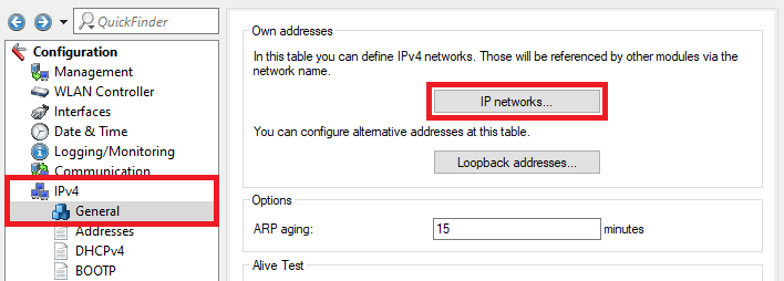 Image Modified Image Modified1.2) In the IP networks dialog, click the Add button to create a new network. 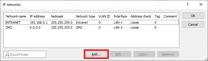 Image Modified Image Modified1.3) Change the following parameters for the GUEST network: - Network name: Enter a descriptive name for the guest network (in this case GUEST).
- IP address: Enter an IP address from an IP address range which is not already in use.
- Netmask: Enter the subnet mask which is associated with the IP address.
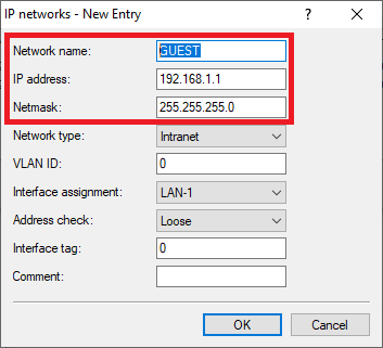 Image Modified Image Modified
1.4) The table IP networks has to appear as follows afterwards: 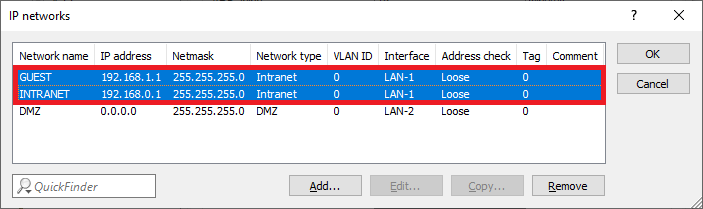 Image Modified Image Modified1.5) Go to the menu IPv4 → DHCPv4 → DHCP networks. 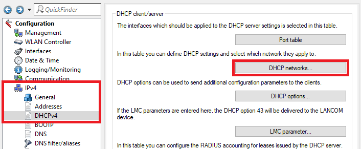 Image Modified Image Modified1.6) Click Add to enter a new entry in the table DHCP networks. 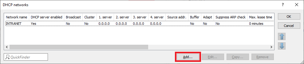 Image Modified Image Modified1.7) Edit the following parameters: - Network name: In the dropdown menu select the network created in step 1.3) (in this example the network GUEST).
- DHCP server enabled: In the dropdown menu select Yes to activate the DHCP server.
| Info |
|---|
If the address 0.0.0.0 is stored for each parameter in the configuration items Addresses for DHCP clients and Name server addresses, the router assigns its own IP address in this network as gateway and DNS server. Furthermore all free IP addresses within this network are used for assigning IP addresses. If necessary you can change the parameters. |
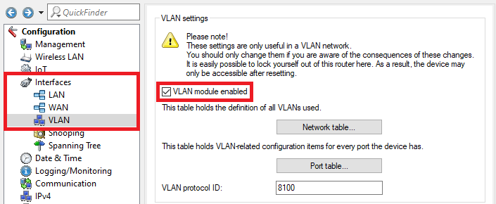
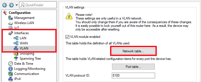
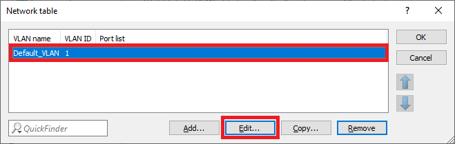
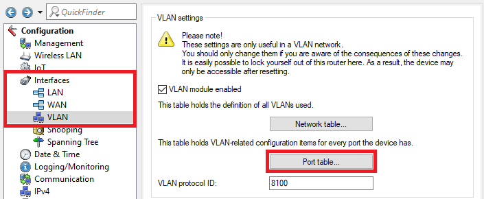
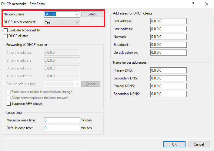 Image Modified Image Modified1.8) The table DHCP networks has to appear as follows afterwards: 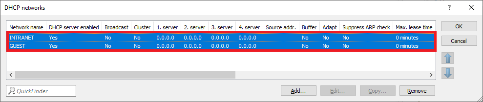 Image Modified Image Modified1.9) Go to the menu Interfaces → VLAN and activate the VLAN module. 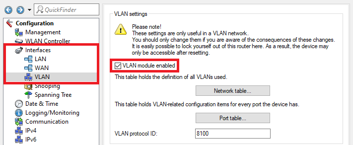 Image Modified Image Modified1.10) Go to the menu Network table. 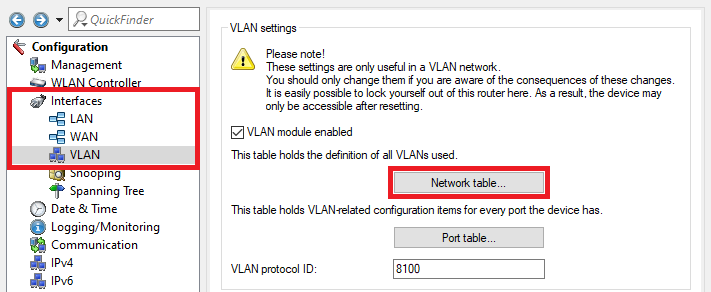 Image Modified Image Modified1.11) Select the entry Default_VLAN and click on the Edit button. 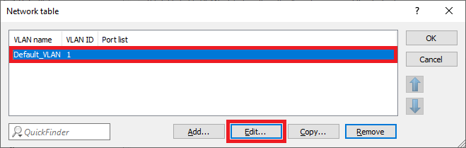 Image Modified Image Modified1.12) Click on the Select button next to Port list to select the interface LAN-1.
| Info |
|---|
The VLAN ID 1 is assigned to the company network. |
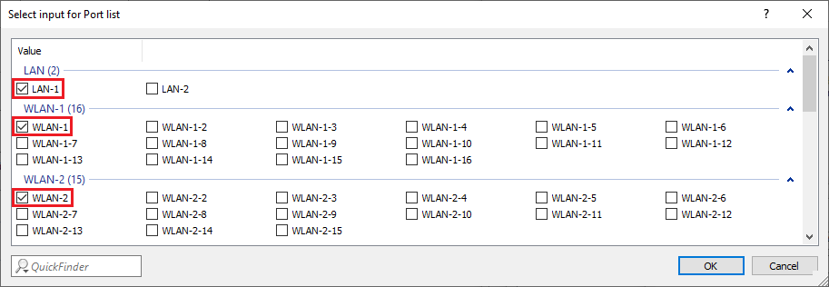
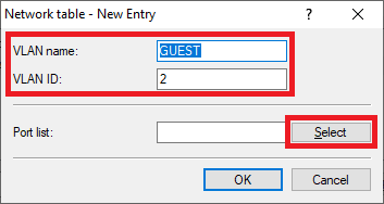
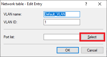 Image Modified Image Modified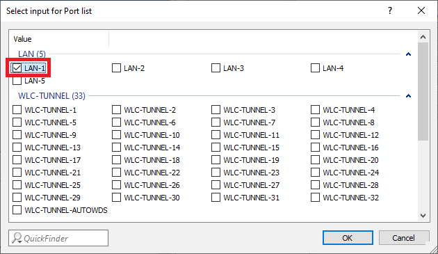 Image Modified Image Modified1.13) Create a new entry and change the following parameters: - VLAN name: Enter a descriptive name for the VLAN (in this example GUEST).
- VLAN ID: Enter the VLAN ID 2.
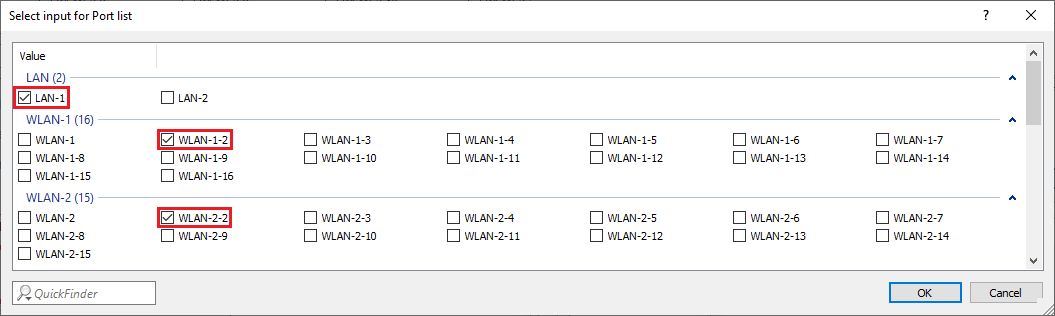
- Port list: Select the locial interface LAN-1.
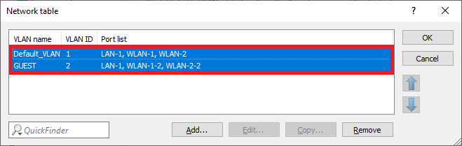
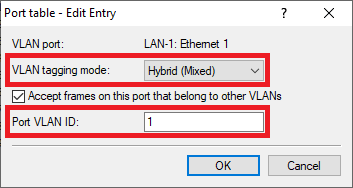
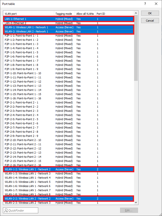
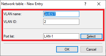 Image Modified Image Modified1.14) The Network table has to appear as follows afterwards: 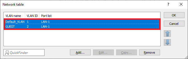 Image Modified Image Modified1.15) Go to the menu Port table. 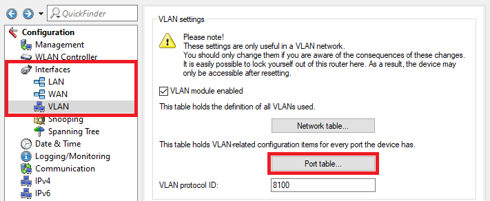 Image Modified Image Modified1.16) Select the VLAN port LAN-1: Local area network 1 and click Edit. 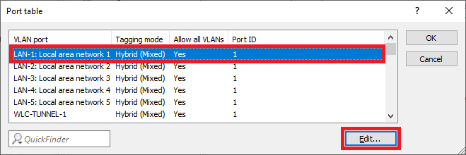 Image Modified Image Modified1.17) Change the following parameters: - VLAN tagging mode: Make sure that the tagging mode Hybrid (Mixed) is selected.
- Port VLAN ID: Make sure that the VLAN ID 1 is used.
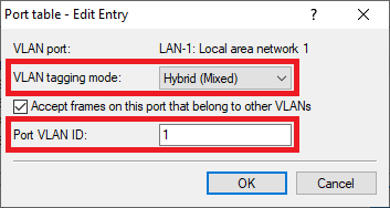 Image Modified Image Modified
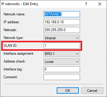
1.18) Go to the menu IPv4 → General → IP networks to add the VLAN IDs to the networks. Image Modified 1.19) Select the network INTRANET and click Edit. 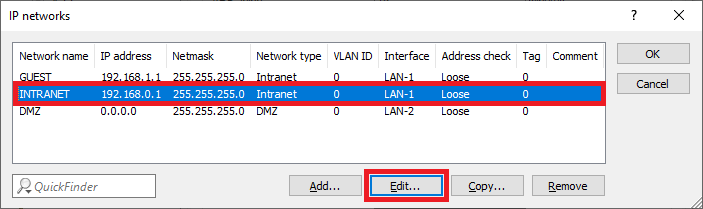 Image Modified Image Modified1.20) Enter the VLAN-ID 1 since it belongs to the company network (INTRANET). 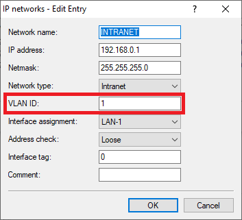 Image Modified Image Modified1.21) Edit the network GUEST and change the following parameters: - VLAN ID: Enter the VLAN ID 2.
- Interface tag: Enter an Interface tag unequal 0, so that the communication between the network GUEST and the network INTRANET is prevented (in this example the tag 1 is used).
| Info |
|---|
Networks that have been given an interface tag can only communicate with networks that share the same interface tag. This also means that the network INTRANET , which has the interface tag 0, is able to communicate with all networks , whatever interface tag they have. This makes it easier to access the guest network from the company network . It is not possible to communicate from the guest network to the company network . |
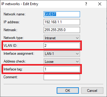 Image Modified Image Modified
1.22) The table IP networks has to appear as follows afterwards: 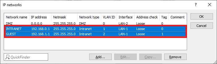 Image Modified Image Modified1.23) The network and VLAN configuration is complete. Write the configuration back into the router.
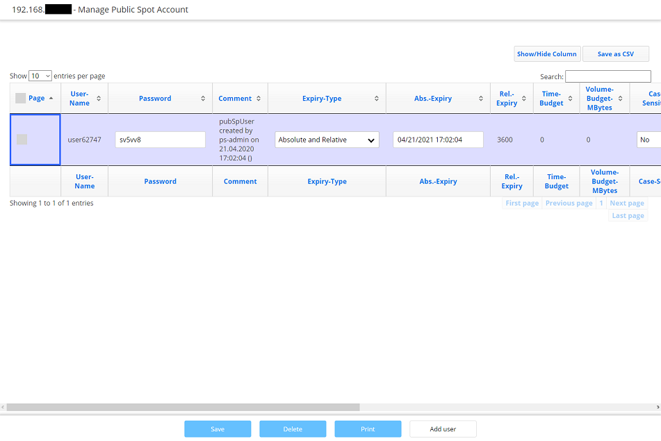
2) Configuring the Public Spot and the RADIUS server on the gateway router 2.1) Go to the menu Public-Spot → Authentication and select the mode Authenticate with name and password.  Image Modified Image Modified2.2) Go to the menu Public Spot → Server → Operational settings. 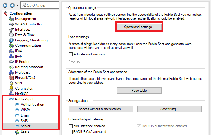 Image Modified Image Modified2.3) Go to the menu Interfaces. 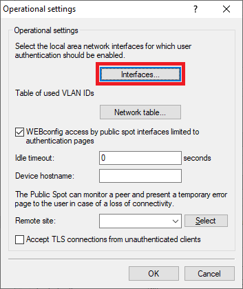 Image Modified Image Modified2.4) Select the Interface for the Public Spot authentication (in this example the interface LAN-1), and click Edit. 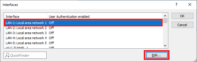 Image Modified Image Modified2.5) Activate the User Authentication for the interface LAN-1: Local area network 1. 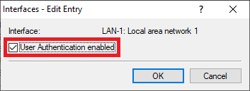 Image Modified Image Modified2.6) Go to the menu Network table to specify which VLAN ID should be used in conjunction with the Public Spot. 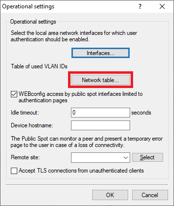 Image Modified Image Modified2.7) Click Add to create a new entry. 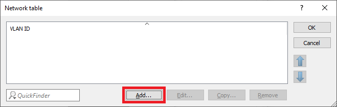 Image Modified Image Modified2.8) Select the VLAN ID 2. 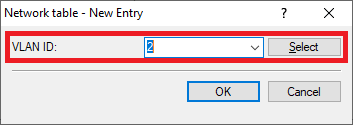 Image Modified Image Modified2.9) Go to the menu Public Spot → Users → RADIUS server to point to the integrated RADIUS server. 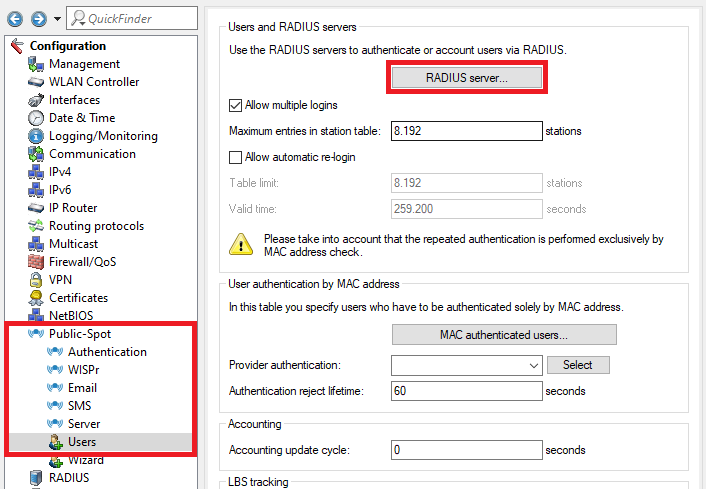 Image Modified Image Modified2.10) Ex factory there is an entry named LOCAL. It points to the integrated RADIUS and Accounting server.
| Info |
|---|
If the entry LOCAL doesn't exist, create an entry and enter any name. |
Make sure that the following parameters are used: - Auth. server address: 127.0.0.1
- Auth. server port: 1812
- Acc. server address: 127.0.0.1
- Acc. server port: 1813
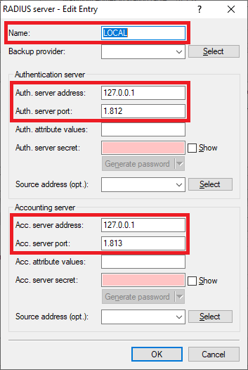 Image Modified Image Modified
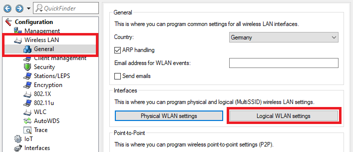
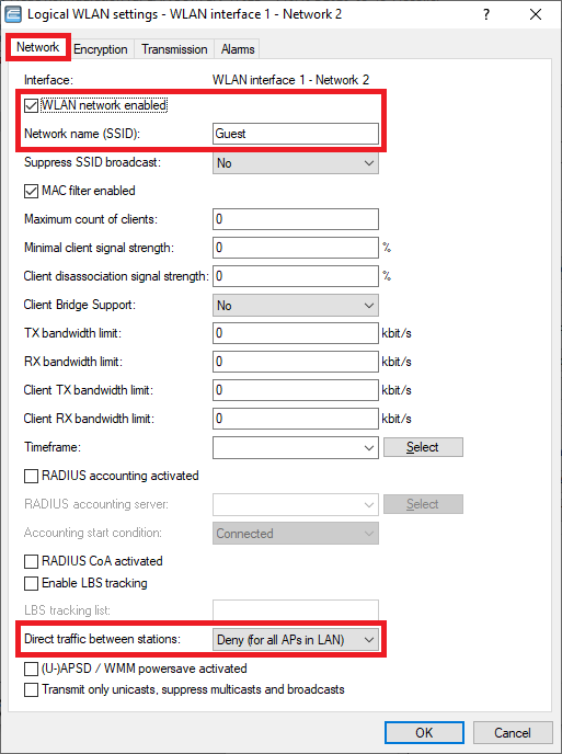
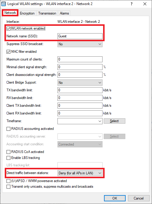
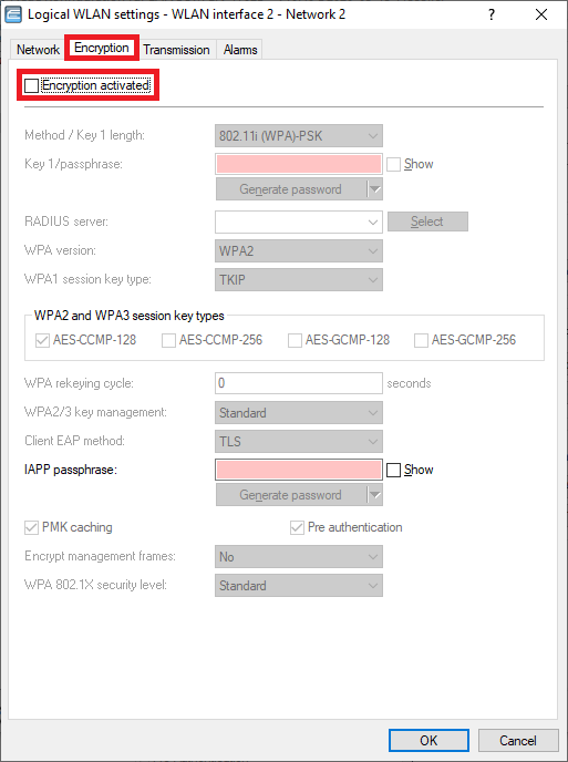
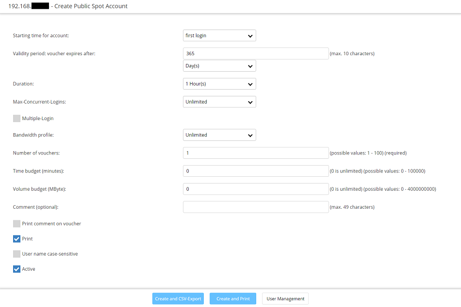
2.11) Go to the menu Public Spot → Wizard → Public Spot SSIDs. 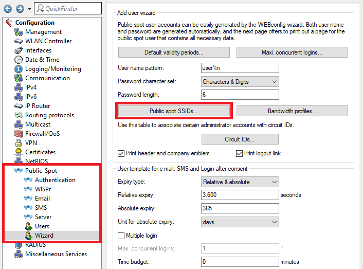 Image Modified Image Modified2.12) Create a new entry and change the following parameters: - SSID: Enter the SSID for the guest network created in step 4.4) (in this example Guest), to print the name of the SSID on the Public Spot voucher.
- SSID selected: Set this option to Yes, in order for the SSID to be printed on the Public Spot voucher whenever a Public Spot user is created and the voucher printed via the setup wizard Create Public Spot Account.
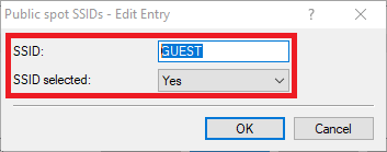 Image Modified Image Modified
2.13) Go to the menu RADIUS → Server and activate the functions RADIUS authentication and RADIUS accounting. 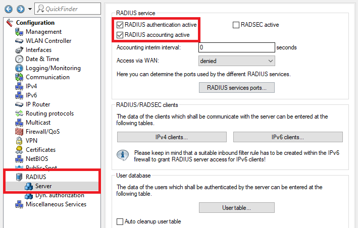 Image Modified Image Modified2.14) Go to the menu RADIUS services ports. 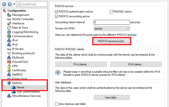 Image Modified Image Modified2.15) Make sure that the Authentication port is set to 1812 and the Accounting port to 1813. 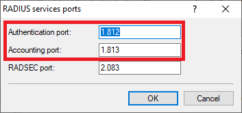 Image Modified Image Modified2.16) The configuration of the Public Spot and the RADIUS server is complete. Write the configuration back into the router.
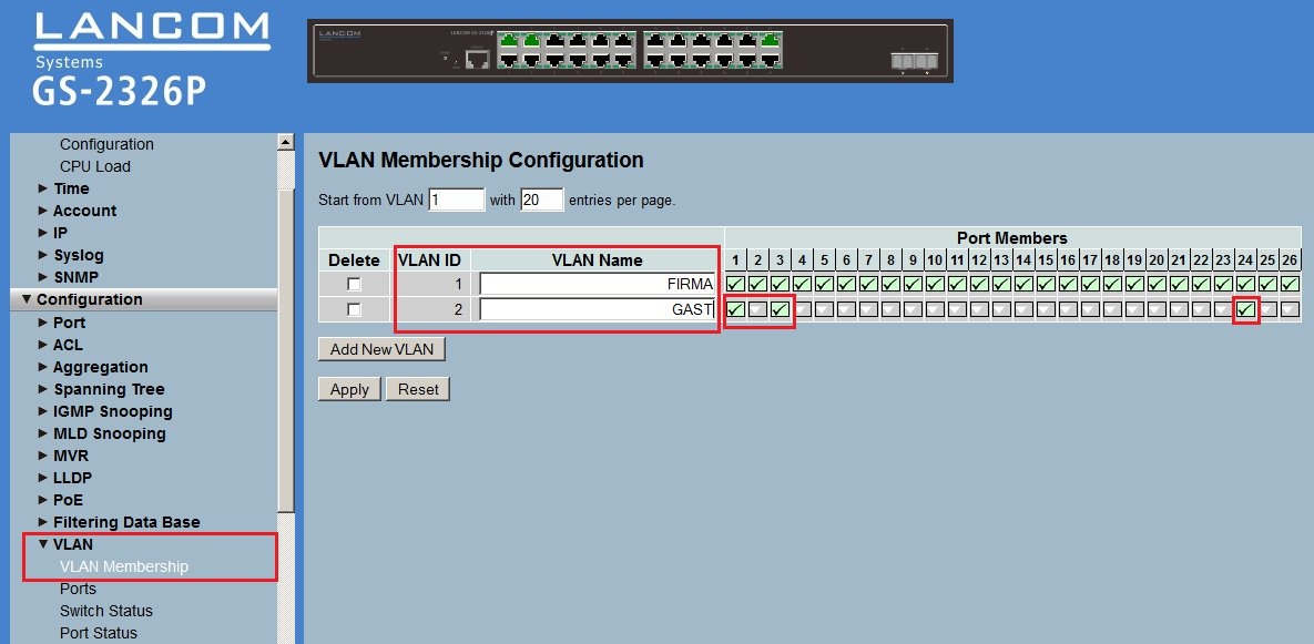
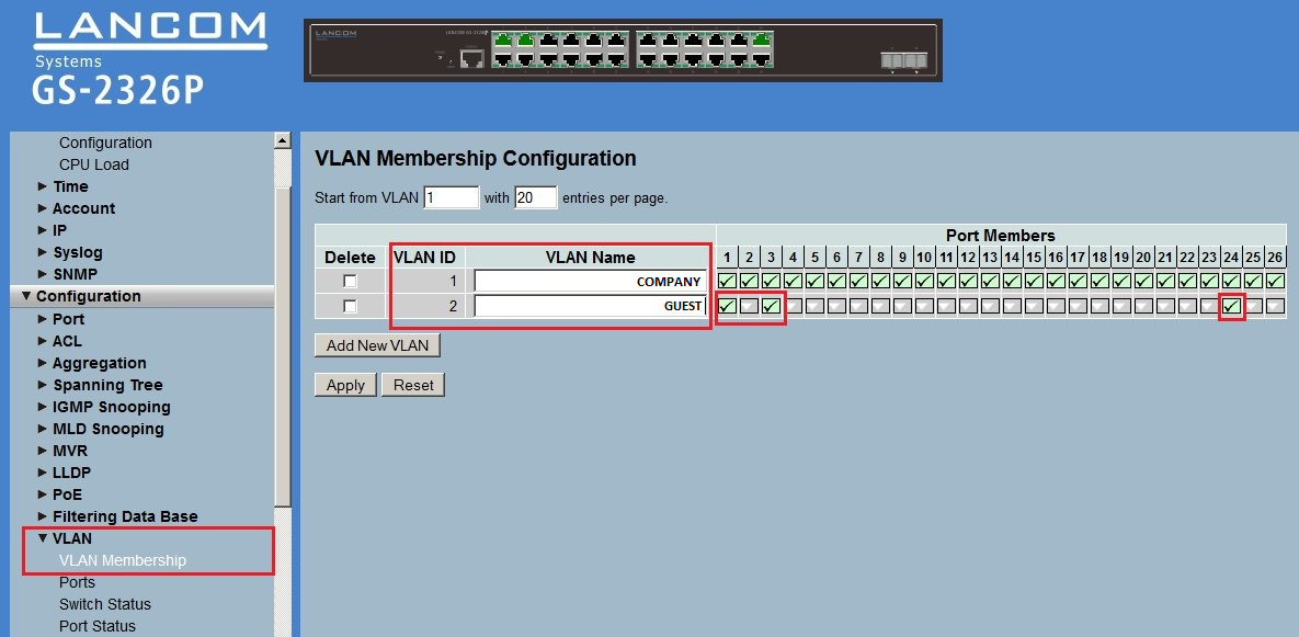
3) Configuring the VLAN on the LANCOM switch: 3.1) Open the configuration of the LANCOM switch in a web browser and go to the menu Configuration → VLAN → VLAN Membership. 3.2) In this example the switch ports should be configured as follows:- LANCOM Access Point at Port 1
- LANCOM gateway router at Port 3
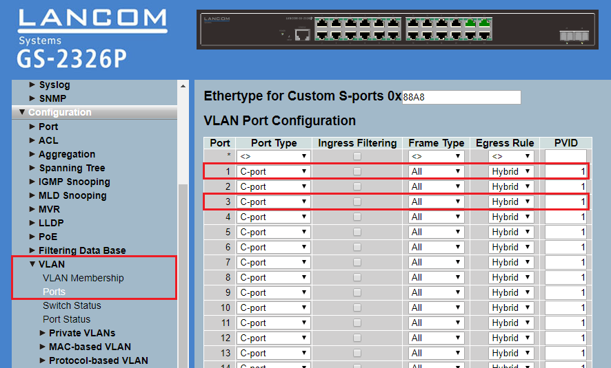
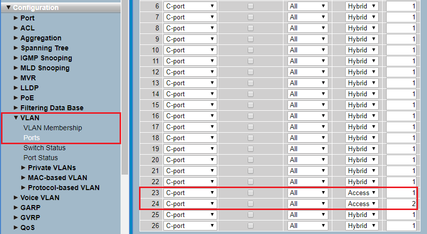
- Port 23 is used for access to the company network (192.168.0.0/24) via LAN.
- Port 24 is used for access to the guest network (192.168.1.0/24) via LAN. The authentication is controlled via the Public Spot.
3.3) Edit the existing Default VLAN and enter the name of the network (in this example COMPANY). 3.4) Add a new VLAN via the button Add New VLAN. Enter the name of the network (in this example GUEST) and enter the VLAN ID 2. 3.5) Tick the checkboxes with the Ports 1, 3 and 24 for the VLAN GUEST. |