| Seiteneigenschaften |
|---|
Description:
In einigen Szenarien ist es notwendig zwecks Erhöhung der Bandbreite oder Schaffung einer Redundanz mehrere Switch-Ports miteinander zu verbinden. Dies lässt sich mit dem Protokoll LACP realisieren Due to higher bandwith or redundancy needs some scenarios require several switch ports to be combined. This can be implemented with the protocol LACP (Link Aggregation Control Protocol).
In diesem Artikel wird beschrieben, wie ein LACP-Trunk auf einem Switch der XS-51xx Serie konfiguriert wird.
| Info |
|---|
LACP unterstützt im Gegensatz zu einem Static Trunk eine dynamische Aushandlung, sodass der Trunk auch bei Ausfall einer Leitung noch funktionsfähig ist. |
Requirements:
This article describes how to configure an LACP Trunk on an XS or GS-45xx series switch.
| Info |
|---|
In contrast to a Static Trunk the feature LACP supports a dynamic negotiation, thus enabling the Trunk to remain active when a line fails. LANCOM Systems therefore recommends to always use LACP when combining switch ports to a trunk. |
Requirements:
- LANCOM aggregation switches of the XS or GS-45xx series
- LCOS SX as of version
- Switch der XS-xxxx Serie
- LCOS SX ab Version 5.00 RU2 (download aktuelle Versionlatest version)
- Beliebiger Web-Browser für den Zugriff auf das WebinterfaceAny Web browser for accessing the webinterface
Procedure:
Führen Sie die folgenden Schritte auf beiden Switches durch, die über einen LACP-Trunk miteinander verbunden werden sollen.
Conduct the following steps on both switches, which are to be connected with each other via an LACP Trunk.
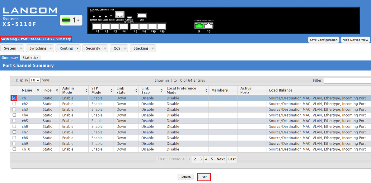
1) Connect to the webinterface of the device, go to the menu 1. Verbinden Sie sich mit dem Webinterface des Gerätes, wechseln in das Menü Switching → Port Channel / LAG → Summary, wählen einen nicht verwendeten select an unused Port Channel aus (in diesem Beispiel this example ch1) und klicken auf and click Edit.
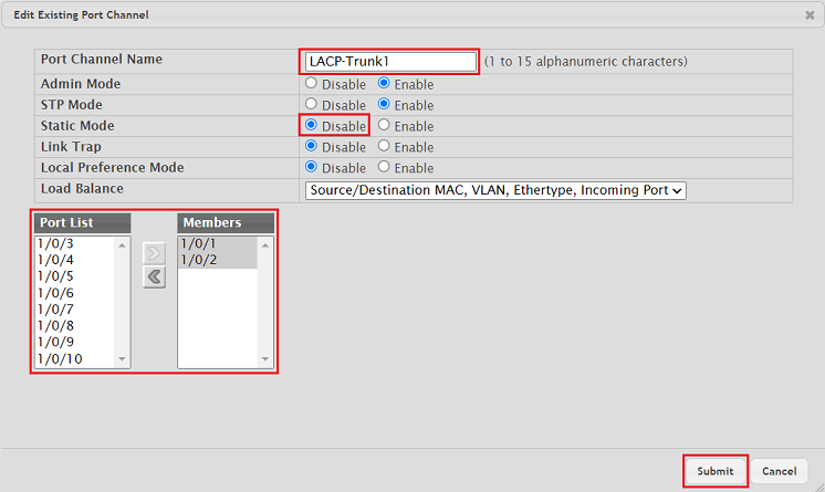
2. Passen Sie die folgenden Parameter an und klicken auf ) Modify the following parameters and click Submit:
- Port Channel Name: Vergeben Sie bei Bedarf einen aussagekräftigen Namen (in diesem Beispiel Enter a descriptive name if necessary (in this example LACP-Trunk1).
- Static Mode: Wählen Sie die Option Disable, damit LACP verwendet wird. Mit der Option Enable wird ein Static Trunk eingerichtetSelect the option Disable in order for LACP to be used. The option Enable sets up a Static Trunk.
- Port List / Members: Fügen Sie mittels der Pfeile aus der Port List die gewünschten Interfaces zu der Gruppe Members hinzuAdd the desired interfaces from the Port List to the Members group via the arrow symbols.
| Info |
|---|
Der Parameter The parameter STP Mode (Spanning Tree Protocol) ist ebenso wie die Funktion as well as the feature STP (Switching → Spanning Tree → Switch) standardmäßig aktiv. Dadurch können die Kabel bereits im Vorfeld gesteckt werden, ohne dass es zu einem Loop kommt, sofern auf dem LACP-Partner (etwa ein weiter XS-51xx Switch) ebenso STP aktiv ist. |
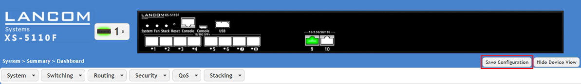
3. Klicken Sie nach erfolgter Konfiguration in der rechten oberen Ecke auf Save Configuration, damit die Konfiguration als Start-Konfiguration gespeichert wird.
| Info |
|---|
Die Start-Konfiguration bleibt auch nach einem Neustart des Gerätes oder einem Stromausfall erhalten. |
are active by default. Therefore the cables can be plugged beforehand without risking a loop if STP is also active on the LACP partner (e.g. another XS-xxxx switch). |
3) With the configuration complete, click on Save Configuration in the top right-hand corner to save the configuration as the boot configuration .
| Info |
|---|
The start configuration is retained even if the device is restarted or there is a power failure. |
Configuring VLAN for an exitisting LACP Trunk:
If VLAN is to be configured on an LACP Trunk, it has to be configured separately for the LACP interface. The first LACP interface is designated as 0/3/1, the second LACP interface is designated as 0/3/2 etc..
| Info |
|---|
The VLAN configuration of the LACP interfaces ist the same as the VLAN configuration of the regular switch ports. |
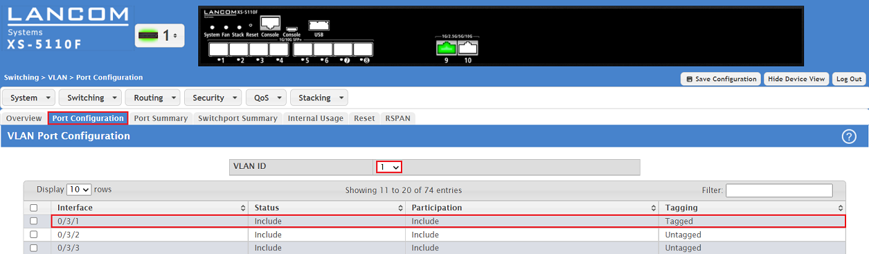
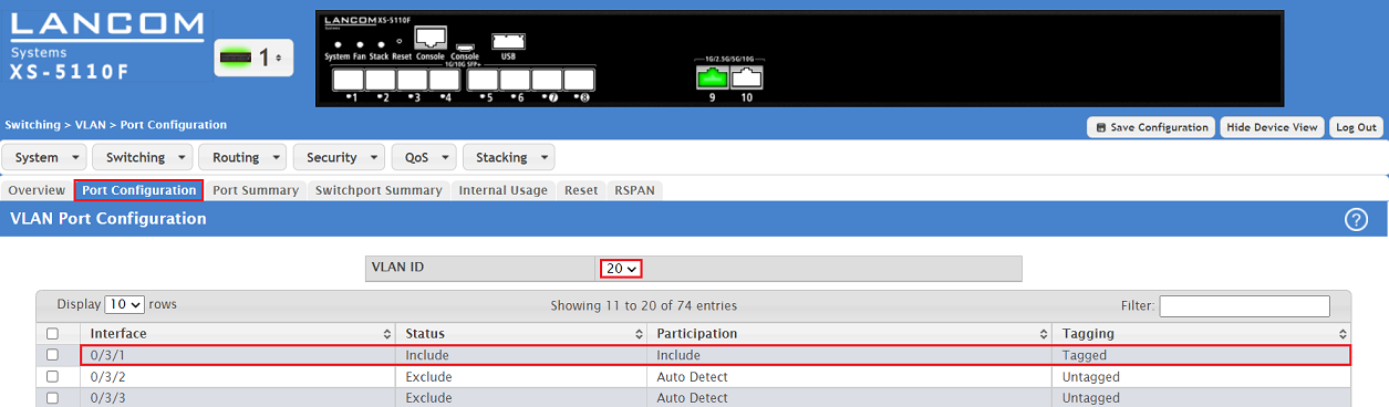
1) Configure the tagging behaviour for all VLANs has to be configured for the desired LACP interface in the tab Port Configuration.
In this example the VLANs 1 and 20 are assigned to the LACP interface 0/3/1 and the necessary parameters for the tagging mode Trunk are configured.
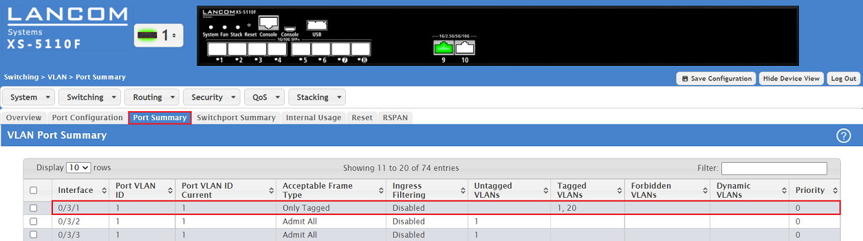
2) Configure the tagging behaviour for the desired LACP interface in the tab Port Summary .
In this example thenecessary parameters for the tagging mode Trunk are configured for the LACP interface 0/3/1.