Description: This article describes how to set up a guest network in a WLAN controller by means of VLAN.
1) An upstream router is operated in the guest network: - In addition to an internal WLAN, an additional WLAN is to be created for guests.
- The internal WLAN should use VLAN 1 and the guest network should use VLAN 2.
- The WLAN controller merely distributes the WLAN configuration to the access points, but is not itself located in the guest network and it does not provide any services there (e.g. DHCP or DNS).
- The separation of the management network and guest network must be performed on the upstream router.

2) The WLAN controller acts as a gateway in the guest network:- In addition to an internal WLAN, an additional WLAN is to be created for guests.
- The internal WLAN should use VLAN 1 and the guest network should use VLAN 2.
- The WLAN controller distributes the WLAN configuration to the access points and is also located in the guest network. In the guest network, it acts as a gateway as well as the DHCP and DNS servers.
- The separation of the management network and guest network must be performed on the WLAN controller.
Procedure:
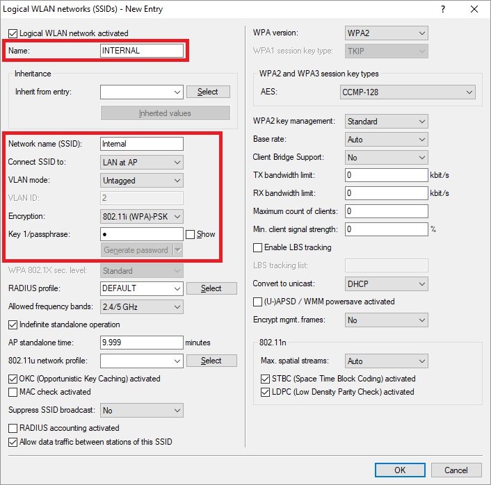
1) An upstream gateway is operated in the guest network: 1.1) Open the configuration of the WLAN controller in LANconfig and navigate to the menu WLAN controller → Profiles → Logical WLAN networks (SSIDs). 1.2) Create a new profile for the internal WLAN and enter the following parameters: - Name: Enter a descriptive name.
- Network name (SSID): Give a name to the SSID, which is displayed to the wireless devices.
- Connect to SSID: Leave the setting LAN at AP.
- VLAN mode: Leave the setting Untagged. This means that VLAN 1 is used implicitly.
- Encryption: Leave the setting 802.11i (WPA)-PSK.
- Key 1/passphrase: Set a WPA key for the WLAN.

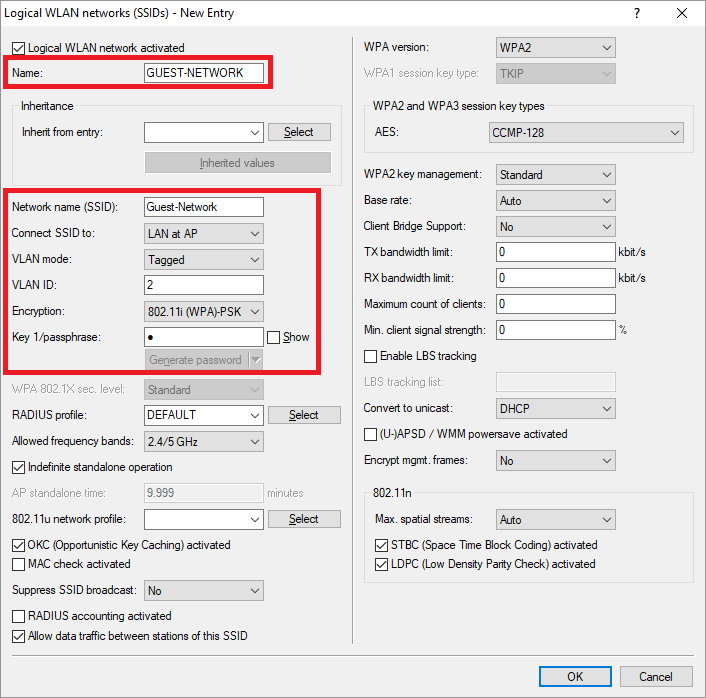
1.3) Create a further profile for the guest network and enter the following parameters: - Name: Enter a descriptive name.
- Network name (SSID): Give a name to the SSID, which is displayed to the wireless devices.
- Connect SSID to: Leave the setting LAN at AP.
- VLAN mode: From the drop-down menu, select Tagged.
- VLAN-ID: Enter the VLAN ID 2 here.
- Encryption: Leave the setting 802.11i (WPA)-PSK.
- Key 1/passphrase: Set a WPA key for the WLAN.

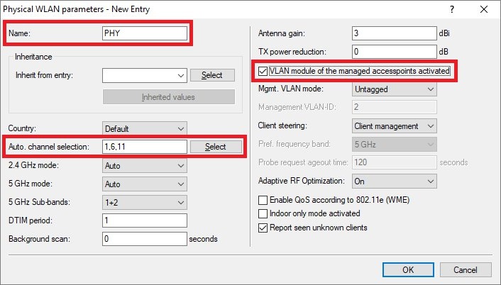
1.4) Navigate to the menu WLAN controller → Profiles → Physical WLAN parameters. 1.5) Create a new entry and enter the following parameters: - Name: Enter a descriptive name.
- Auto. channel selection: Set a fixed channel pattern for the 2.4-Ghz band (e.g. 1, 6, 11).
- Set a checkmark for VLAN module of the managed access points activated.

1.6) Navigate to the menu WLAN controller → Profiles → WLAN profiles. 1.7) Create a new entry and enter the following parameters: - Profile name: Enter a descriptive name.
- WLAN network list: Select the Logical WLAN networks (SSIDs) that you created in steps 1.2 and 1.3.
- Physic. WLAN parameters: Using the drop-down menu, select the physical WLAN parameters created in step 1.5.
1.8) You can now write the configuration back to the device. This concludes the configuration steps on the WLAN controller.
2) The WLAN controller acts as a gateway in the guest network: The basic configuration of scenario 2 is done the same way as for scenario 1. However, scenario 2 requires some additional settings to be made.
2.1) Creating a guest network and activating the DHCP server: 2.1.1) Switch to the menu IPv4 → General → IP networks. 2.1.2) Create a new entry for the Guest Network and enter the following parameters: - Network name: Enter a descriptive name.
- IP address: Enter an IP address from the IP address range intended for the guest network.
- Netmask: Enter the subnet mask intended for the guest network.
- VLAN-ID: Enter the VLAN ID 2 intended for the guest network.
2.1.3) Switch to the menu IPv4 → DHCPv4 → DHCP networks. 2.1.4) Create a new entry for the Guest Network and enter the following parameters: - Network name: From the drop-down menu, select the guest network created in step 2.1.2.
- DHCP server enabled: Select Yes from the drop-down menu.
2.2) Use the firewall to block communication from the guest network to the internal network and allow DNS requests from the guest network: 2.2.1) Navigate to the menu Firewall/QoS → IPv4 rules → Rules. 2.2.2) Create a new rule and, on the General tab, give it a descriptive name. 2.2.3) Change to the Actions tab and make sure, that the action object REJECT is in place. 2.2.4) Change to the Stations tab, choose connections from the following stations and click Add → Add custom station. 2.2.5) From the drop-down menu for the Network name, select the Guest Network. 2.2.6) Set the Connection destination to the item connections to the following stations and click Add → LOCALNET. 2.2.7) Click OK to create the firewall rule. 2.2.8) Select the firewall rule created in steps 2.2.2 - 2.2.7 and click on Copy to create an additional firewall rule, which allows DNS requests from the guest network. 2.2.9) On the General tab, adjust the Name of the rule accordingly. 2.2.10) Switch to the Actions tab, delete the object REJECT and add the object ACCEPT instead. 2.2.11) Navigate to the Services tab. Under Protocols/target services select the item the following protocols/target services and click Add. 2.2.12) Select the protocol DNS. 2.2.13) You can now write the configuration back to the device. This concludes the configuration steps on the WLAN controller. |