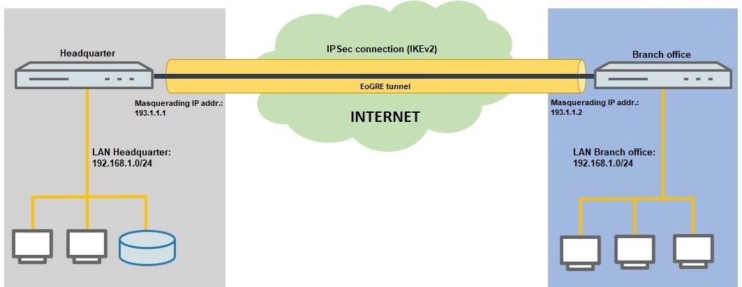
Description:
In certain scenarios, two locations connected via VPN use networks with the same IP address range, so that communication takes place on layer 2 (MAC address) instead of layer 3 (routing). With a normal VPN connection the sites must have different IP address ranges, so linking these networks makes routing essential. With help of an EoGRE tunnel (Ethernet-over-GRE), two sites can be interconnected by a GRE tunnel (Generic Routing Encapsulation) and packets are transmitted on layer 2. This means that the same IP address range can be used at both sites.
Since a GRE tunnel operates unencrypted, LANCOM Systems recommends that the data traffic should be encrypted, for example by operating an IKEv2 connection within the EoGRE tunnel.
This article describes how two routers that use the same IP address range are set up to operate an EoGRE tunnel and an IKEv2 connection.
Please note that broadcast and multicast packets are sent over an EoGRE tunnel. This can increase the load on the network! |
Requirements:
Scenario:

Procedure:
1) Setting up the IKEv2 connection on the two routers:
Use the setup wizard to set up the VPN connections on the two routers. This is described in the following Knowledge Base article:
Configuring an IKEv2 VPN connection between two LANCOM routers using the Setup Wizard (IPv4)
2) Configuring EoGRE tunnel on the router at the headquarters:
2.1) Using LANconfig, connect to the router at the headquarters, switch to the menu Interfaces → LAN → Ethernet ports and check which logical LAN interface is assigned to the Ethernet port used for the local network (in this example, the local network is connected with the port ETH 1; the physical port ETH 1 has the logical interface LAN-1 assigned to it).
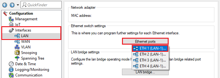
2.2) Navigate to the menu Interfaces → LAN → LAN bridge.
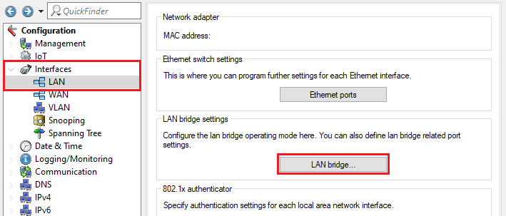
2.3) Make sure that the option Connect by using a bridge (default) is selected. Then go to the Port table menu.
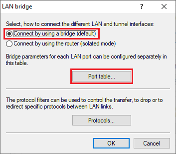
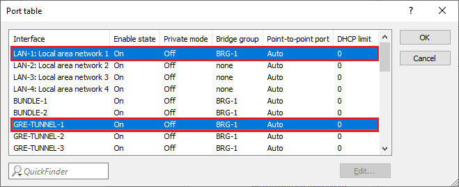
2.4) Make sure that the used logical LAN interface (see step 2.1) and the GRE tunnel (see step 2.6) are both set with the same bridge group (in this example BRG-1).
In the case of a WLAN router, the used WLAN interface also has to be in the same bridge group (assuming that the WLAN is operated in the network). |
2.5) Switch to the menu Communication → Remote sites → GRE tunnel.
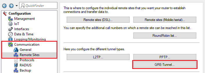
2.6) Click EoGRE tunnel and select a previously unused GRE tunnel (in this example GRE-Tunnel-1).

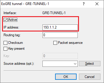
2.7) Activate the GRE tunnel and set the IP address to an address from a previously unused IP address range. This is the address where the end point of the GRE tunnel at the branch office should be reached (in this example 193.1.1.2).
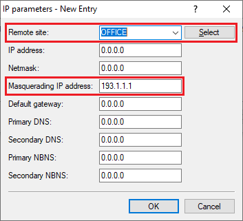
2.8) Navigate to the menu Communication → Protocols → IP parameters.

2.9) Add a new entry, set the Remote site to the VPN connection set up in step 1 (in this example OFFICE) and set the Masquerading IP address to an IP address that is used to mask the local network via the EoGRE tunnel to the branch office (in this example 193.1.1.1).
Unlike IKEv1, IKEv2 does not use an extranet address, so masking with IKEv2 has to be implemented in the IP parameters. |
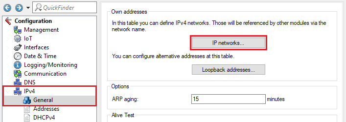
2.10) Switch to the menu IPv4 → General → IP networks.
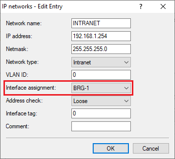
2.11) For the local network, make sure that the Interface assignment is set to the relevant bridge group (in this example BRG-1).
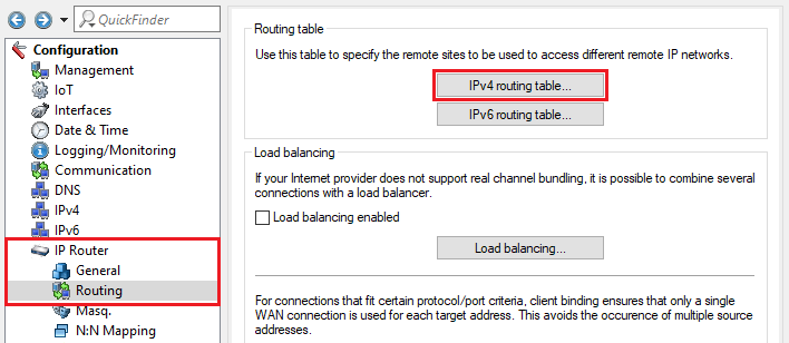
2.12) Navigate to the menu IP router → Routing → IPv4 routing table.
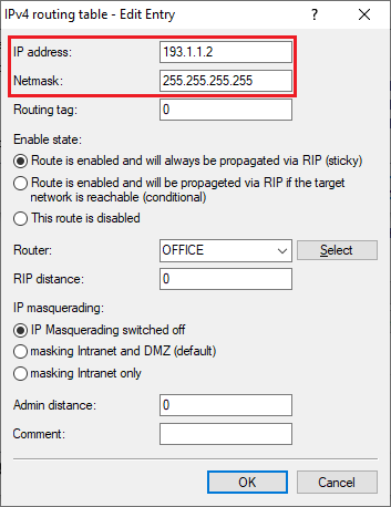
2.13) Choose the routing entry that was created for the VPN connection to the branch office and click Edit.

2.14) Change the following parameters:
2.15) This concludes the configuration of the EoGRE tunnel for the router at the headquarters, so write the configuration back to the device.
3) Configuring EoGRE tunnel on the router at the branch office:
3.1) Using LANconfig, connect to the router at the branch office, switch to the menu Interfaces → LAN → Ethernet ports and check which logical LAN interface is assigned to the Ethernet port used for the local network (in this example, the local network is connected with the port ETH 1; the physical port ETH 1 has the logical interface LAN-1 assigned to it).

3.2) Navigate to the menu Interfaces → LAN → LAN bridge.

3.3) Make sure that the option Connect by using a bridge (default) is selected. Then go to the Port table menu.

3.4) Make sure that the logical LAN interface (see step 3.1) and the GRE tunnel (see step 3.6) are both set with the same bridge group (in this example BRG-1).
In the case of a WLAN router, the used WLAN interface also has to be in the same bridge group (assuming that the WLAN is operated in the network). |

3.5) Switch to the menu Communication → Remote sites → GRE tunnel.

3.6) Click EoGRE tunnel and select a previously unused GRE tunnel (in this example GRE-Tunnel-1).

3.7) Activate the GRE tunnel and set the IP address to an address from the same IP address range assigned to the router in the headquarter in step 2.7. This is the address where the end point of the GRE tunnel at the headquarters should be reached (in this example 193.1.1.1).
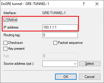
3.8) Navigate to the menu Communication → Protocols → IP parameters.

3.9) Add a new entry, set the Remote site to the VPN connection set up in step 1 (in this example HEADQUARTERS) and set the Masquerading IP address to an IP address that is used to mask the local network via the EoGRE tunnel to the headquarters (in this example 193.1.1.2).
Unlike IKEv1, IKEv2 does not use an extranet address, so masking with IKEv2 has to be implemented in the IP parameters. |
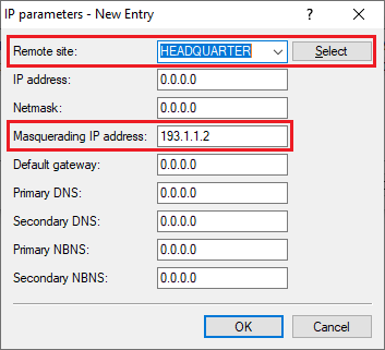
3.10) Switch to the menu IPv4 → General → IP networks.

3.11) For the local network, make sure that the Interface assignment is set to the relevant bridge group (in this example BRG-1).
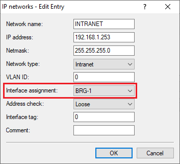
3.12) Navigate to the menu IP router → Routing → IPv4 routing table.

3.13) Choose the routing entry that was created for the VPN connection to the headquarters and click Edit.

3.14) Change the following parameters:
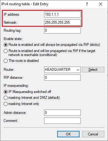
3.15) This concludes the configuration of the EoGRE tunnel for the router at the branch office, so write the configuration back to the device.