Description:
This document describes the configuration a VRRP scenario (Virtual Router Redundancy Protocol) with two LANCOM routers and a single Internet connection.
Information:
- Operating an upstream router to provide the Internet connection results in a
single point of failure
- , which is why this scenario is unsuitable for ensuring redundancy of the Internet connection. Should the upstream switch fail then none of the LANCOM routers in the VRRP scenario can establish an Internet connection.
Requirements:
Scenario:
Scenario:
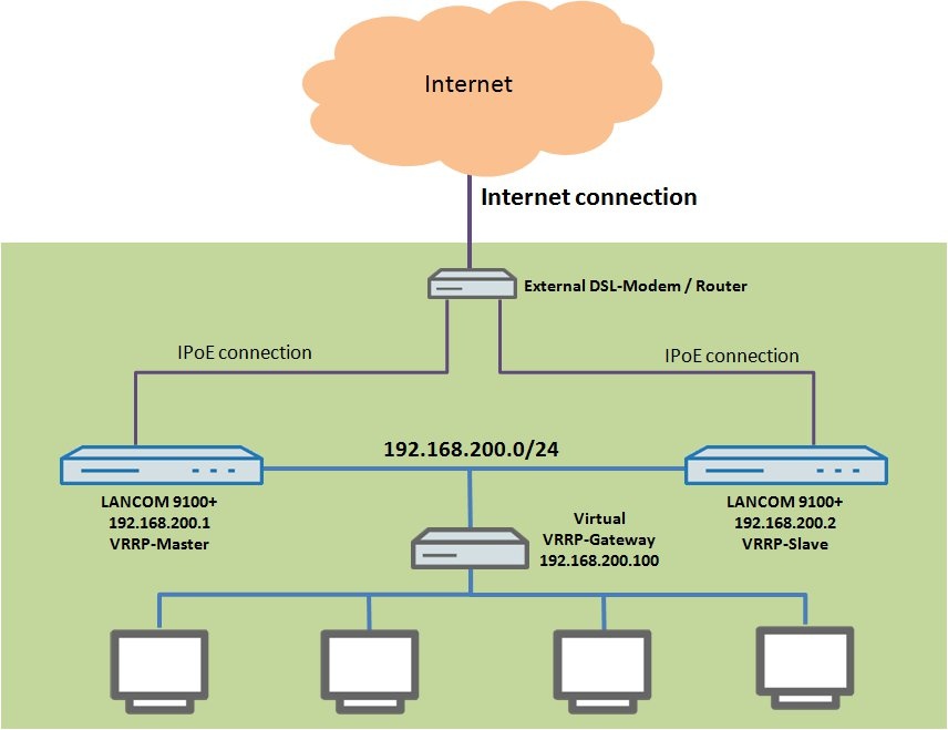
In this scenario a VRRP group is to be formed with two LANCOM routers. Each of the two LANCOM routers is a LANCOM 9100+.
- An Internet connection is provided by an upstream router.
- The two LANCOM 9100+ routers connect to the Internet by IPoE.
- The two LANCOM routers are located in the same local area network with the address range 192.168.200.0/24 and act as a DHCP servers for the local network.
- One LANCOM 9100+ is to be configured as the master router (VRRP master) and the other LANCOM 9100+ acts as a backup (VRRP standby).
Procedure:
1) Setting up the Internet connection:
You must perform the following configuration steps identically on both routers. Set up the Internet connection first on the VRRP master and then on the VRRP standby.
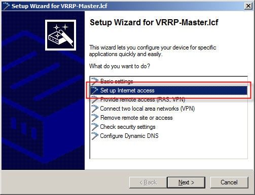
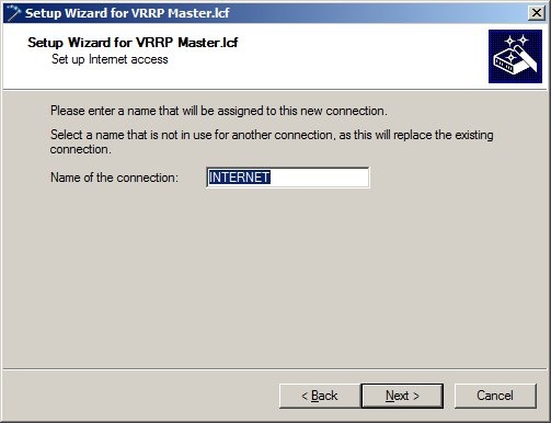
1.1) Launch the Setup Wizard in LANconfig and select the option Set up Internet access.
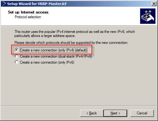
1.2) Select the option Create a new connection (only IPv4).
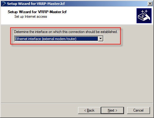
1.3) For the interface, select the option Ethernet interface (external modem/router).
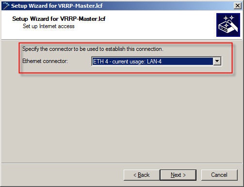
1.4) In this example the external DSL modem is connected to the Ethernet port ETH 4.
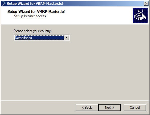
1.5) Select your country.
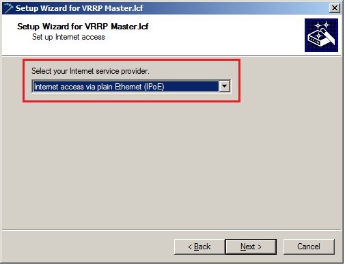
1.6) The Internet service provider is set to the option Internet access via plain Ethernet (IPoE).
1.7) In the following dialog, accept the default settings.
1.8) Because the upstream router in this example automatically supplies the IP parameters for the IPoE connection, in the following dialog select Obtain IP parameters automatically from DHCP server.
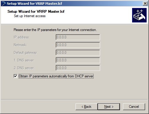
Information:
- If the upstream router or the cable modem is not configured as a DHCP server, you must disable the
Obtain IP parameters automatically from the DHCP server
- option and enter the IP parameters into the fields manually.
IP address:
public IP address
- for use in the WAN, as communicated to you by your Internet provider.
Netmask:
- Enter the netmask provided to you by your Internet provider.
Default gateway:
public IP address
- as used by the upstream router or cable modem.
1st DNS server:
- IP address used by the first DNS server used for the Internet connection. Enter the IP address provided to you by your Internet provider.
2nd DNS server:
- IP address used by the second DNS server used for the Internet connection. Enter the IP address provided to you by your Internet provider.
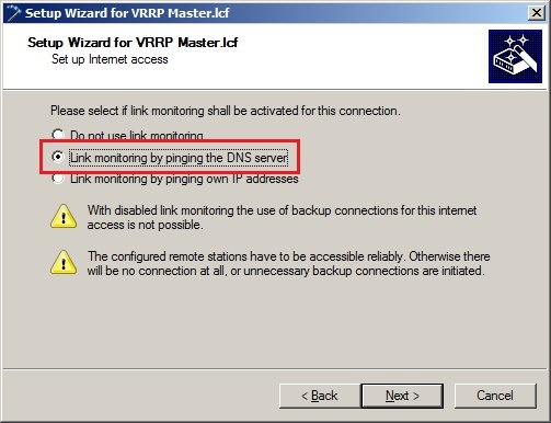
1.9) Choose the Option Link monitoring by pinging the DNS server.
1.10) Exit the setup Internet connection wizard with the Finish button. The configured values are then written to the LANCOM router.
1.11) Open the configuratation of the LANCOM router in LANconfig and go to the menu Configuration -.> Communications -> Remote sites (DSL).
1.12) Open the entry for the previously configured DSL remote site and select User-defined in the field MAC address type.
1.13) In the MAC Address field, you must enter the MAC address of the other LANCOM router in the VRRP group (here the second LANCOM 9100+ VPN) so that in case of a backup the upstream router must not learn the MAC address of a backup device.
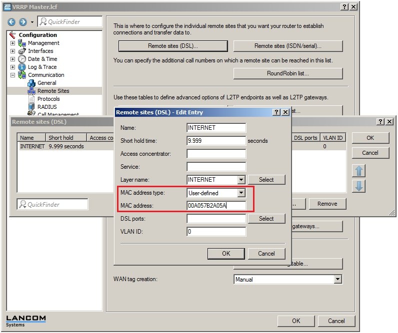
1.14) Write the changes back into the LANCOM router.
1.15) Carry out exactly the same configuration steps to set up an Internet connection (1.1 up to 1.14) on the backup router. Use the same Internet access data.
2) Configuring the VRRP function:
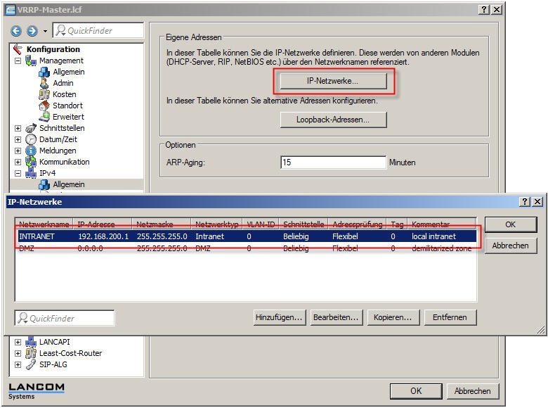
2.1) In the menu Configuration-> IPv4-> IP networks, both LANCOM routers must be configured so that they belong to the same local area network.
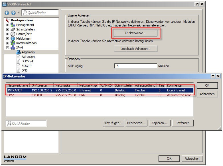
In this example, this is the local network with the address range 192.168.200.0/24. The IP address of the first LANCOM 9100+ is 192.168.200.1 and the other LANCOM 9100+ has the IP address 192.168.200.2.
VRRP master (LANCOM 9100+):
VRRP standby (LANCOM 9100+):
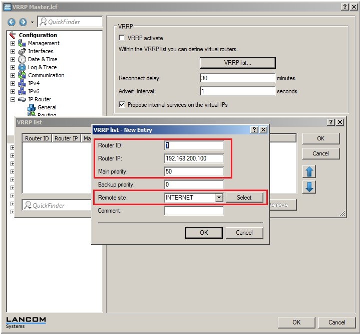
2.2) To make use of the VRRP functionality, both devices require the VRRP activate option to be enabled in the menu Configuration-> IP router-> VRRP.
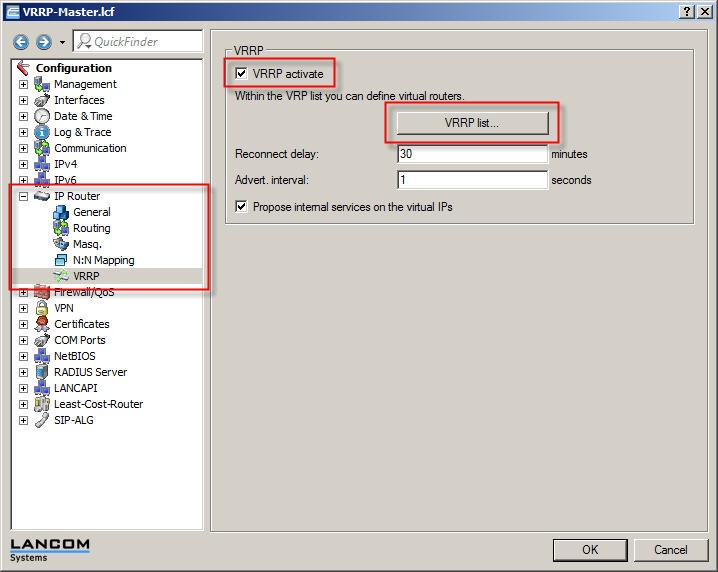
It is important for the VRRP list to be configured on both LANCOM routers. Particular attention must be paid to the values for the Router ID, the Router IP, and the Priority.
Router ID:
- The devices to be collected into a VRRP group must have
the same router ID
- Values may be entered between 1 and 255.
Router IP:
- This IP address is the virtual router IP which the network clients are to use as their gateway address.
- This IP address must be available in the IP address range of both devices. In this
example
192.168.200.100
Priority:
- In a VRRP group, the device with the higher priority is the master, i.e. it handles all of the router tasks exclusively. If the master router or its Internet connection should fail, then the device with the next lower priority takes over the routing tasks.
Information:
- Values may be entered between 0 and 255. Please note that the values 0 and 255 are of special significance. The value
0 disables VRRP completely
- . The value 255 is only used when the address of the virtual router (router IP) is the same as the "real" IP address of the device.
Remote site:
- In this configuration item, the
Internet remote site
- configured for each of the respective devices must be selected.
2.3) Now open the VRRP list on each device and add a new entry:
VRRP master (LANCOM 9100+):
VRRP standby (LANCOM 9100+):

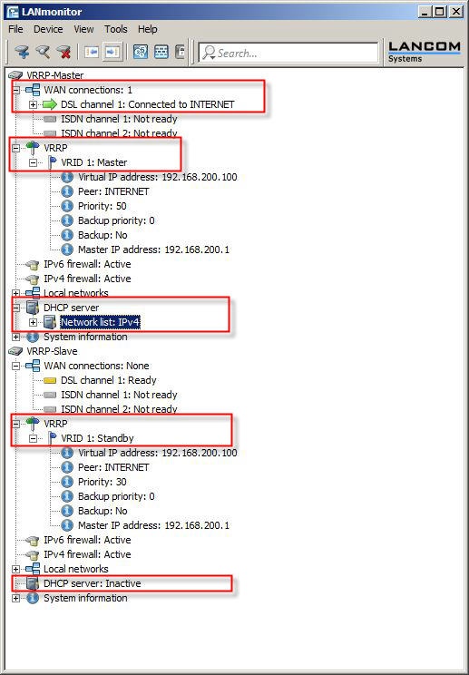
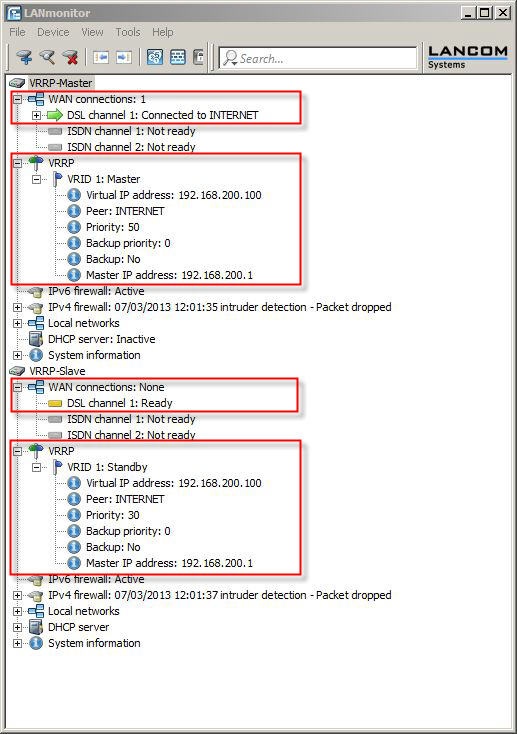
2.4) Save the configuration to the two devices. LANmonitor now has a new item VRRP. Here you can check the settings and how they are functioning.
- The VRRP master has established the Internet connection and is operating as a DHCP server.
- The VRRP standby is in standby mode. The Internet connection on the standby device is inactive.

3) Functional testing of the error scenario:
Since the VRRP becomes active in case of an Internet connection failure or in case a LANCOM router should fail, the following steps are required to check the functionality:
3.1) Testing in case of a DSL connection failure:
3.1.1) Unplug the DSL cable from the master router. As soon as the line polling detects a loss of the Internet connection, the backup router is activated. Then test whether the Internet can be accessed from a client on the local network.

3.1.2) Plug-in the DSL cable to the master router again. The master router becomes active again after the reconnect delay time.
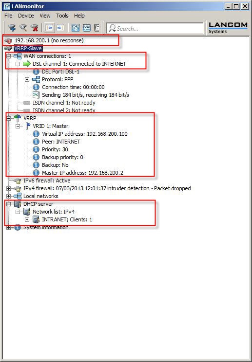
3.2) Testing the failure of the master router:
3.2.1) Switch off the master router at the mains switch. The backup router becomes active after the delay time. The DHCP function is also executed by the backup router.
Test whether the Internet can be accessed from a client on the local network.
3.2.2) Switch the master router on again at the mains switch. The master router becomes active again after the reconnect delay time.
The master router takes over the Internet connection again and also the DHCP function.