Description:
Due to higher bandwith or redundancy needs some scenarios require several switch ports to be combined. This can be implemented with the protocol LACP (Link Aggregation Control Protocol).
This article describes how to configure an LACP Trunk on a switch with LCOS SX 5.xx.
In contrast to a Static Trunk the feature LACP supports a dynamic negotiation, thus enabling the Trunk to remain active when a line fails. LANCOM Systems therefore recommends to always use LACP when combining switch ports to a trunk.
Requirements:
- One of the following LANCOM switch models:
- XS-51xx / XS-6128QF
- GS-45xx / XS-45xx
- CS-8132F
- YS-7154CF
- LCOS SX as of version 5.00 for XS-51xx / XS-6128QF (download latest version)
- LCOS SX as of version 5.20 for GS-45xx / XS-45xx (download latest version)
- LCOS SX as of version 5.30 for CS-8132F and YS-7154CF (download latest version)
- Any Web browser for accessing the webinterface
Procedure:
Conduct the following steps on both switches, which are to be connected with each other via an LACP Trunk.
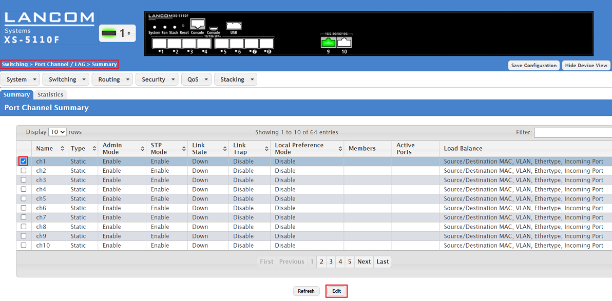
1) Connect to the webinterface of the device, go to the menu Switching → Port Channel / LAG → Summary, select an unused Port Channel (in this example ch1) and click Edit.
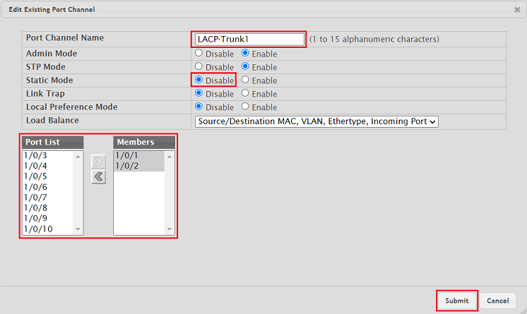
2) Modify the following parameters and click Submit:
- Port Channel Name: Enter a descriptive name if necessary (in this example LACP-Trunk1).
- Static Mode: Select the option Disable in order for LACP to be used. The option Enable sets up a Static Trunk.
- Port List / Members: Add the desired interfaces from the Port List to the Members group via the arrow symbols.
The parameter STP Mode (Spanning Tree Protocol) as well as the feature STP (Switching → Spanning Tree → Switch) are active by default. Therefore the cables can be plugged beforehand without risking a loop if STP is also active on the LACP partner (e.g. another XS-xxxx switch).
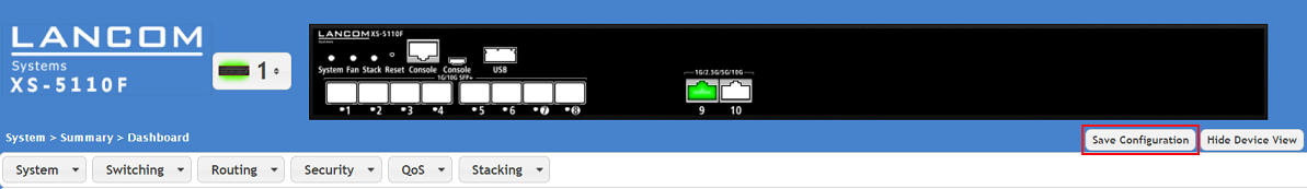
3) With the configuration complete, click on Save Configuration in the top right-hand corner to save the configuration as the boot configuration .
The start configuration is retained even if the device is restarted or there is a power failure.
Configuring VLAN for an exitisting LACP Trunk:
If VLAN is to be configured on an LACP Trunk, it has to be configured separately for the LACP interface. The first LACP interface is designated as 0/3/1, the second LACP interface is designated as 0/3/2 etc..
The VLAN configuration of the LACP interfaces ist the same as the VLAN configuration of the regular switch ports.
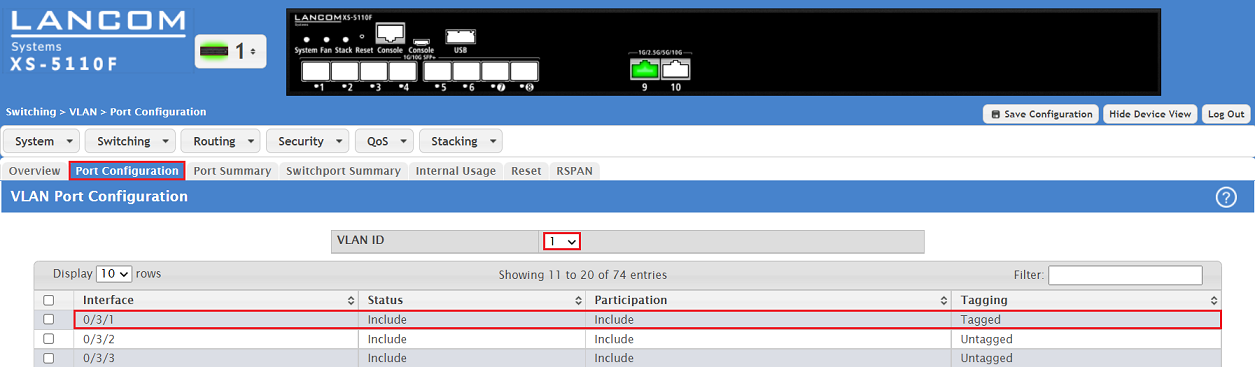
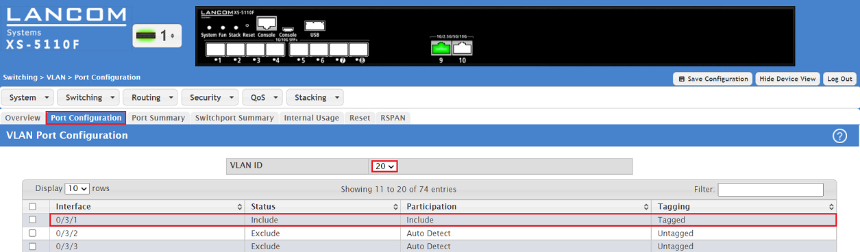
1) Configure the tagging behaviour for all VLANs has to be configured for the desired LACP interface in the tab Port Configuration.
In this example the VLANs 1 and 20 are assigned to the LACP interface 0/3/1 and the necessary parameters for the tagging mode Trunk are configured.
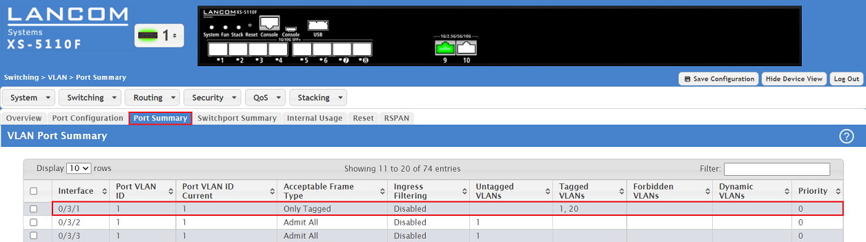
2) Configure the tagging behaviour for the desired LACP interface in the tab Port Summary .
In this example the necessary parameters for the tagging mode Trunk are configured for the LACP interface 0/3/1.