Description:
This document describes how to configure stacking on the LANCOM switches with LCOS SX 5.xx
No loadbalancing is done by aggregating the individual stacking ports and thus there are no performance gains.
You can find additional information in the techpaper:
Requirements:
- One of the following LANCOM switch models:
- XS-51xx / XS-6128QF
- GS-45xx / XS-45xx
- YS-7154CF
- LCOS SX as of version 5.00 for XS-51xx / XS-6128QF (download latest version)
- LCOS SX as of version 5.20 for GS-45xx / XS-45xx (download latest version)
- LCOS SX as of version 5.30 for YS-7154CF (download latest version)
- Identical firmware version on all switches in the stack
- Any web browser for accessing the webinterface
- The switches need to have an IP address (either assigned statically or obtained from a DHCP server).
Important information about stacking:
- Devices of the XS-51xx / XS-61xx series only support stacking on certain ports. These are marked on the front panel accordingly (white circle with black number). Information is also available in the Quick Reference Guide enclosed with the switch.
- When configuring Stacking on an XS-6128QF, please refer to the Knowledge Base article LANCOM Techpaper on configuration options for the aggregation switch LANCOM XS-6128QF regarding the different port configuration possibilities.
- How to perform a firmware update for switches in a stack is described in this article.
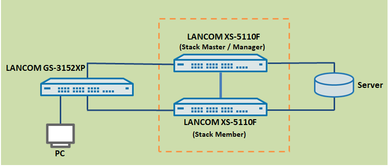
Scenario:
- This scenario collects two LANCOM aggregation switches (in this case LANCOM XS-5110F) into a stack.
- Further IT infrastructure is then connected to the stack, e.g. a LANCOM fully managed access switch of the type LANCOM GS-3xxx and a network server
Procedure:
Step 1: Configuring stacking on the switch ports
Do not connect the switches with the stacking cables yet but configure stacking on the switches first !
When configuring stacking the stacking ports can be operated exclusively with the native port speed. Therefore with stacking it is not possible to use an SFP module with a lower speed than the native port speed on these ports (e.g. a 1 GBit SFP module on a 10 GBit port).
1.1 Open the configuration of the switches that are to operate in the stack and navigate to the menu Stacking → Base → Port Configuration.
1.2 Select the port to be used for stacking.
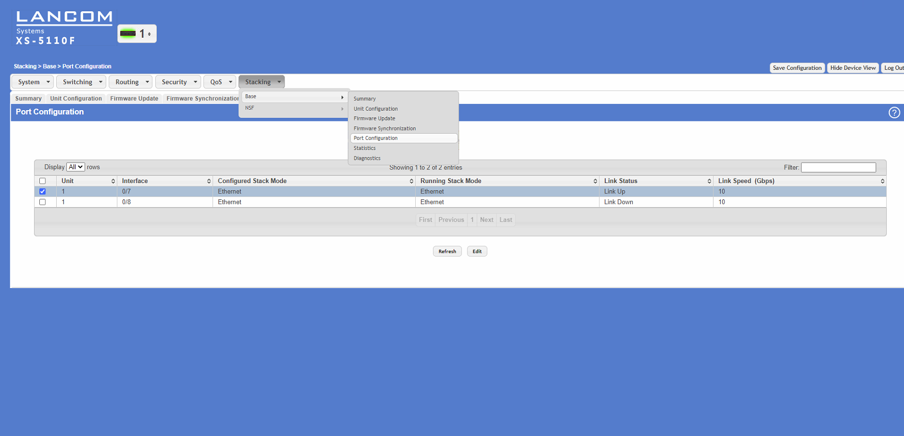
1.3 Activate the stacking feature by changing the interface mode from Ethernet to Stack.
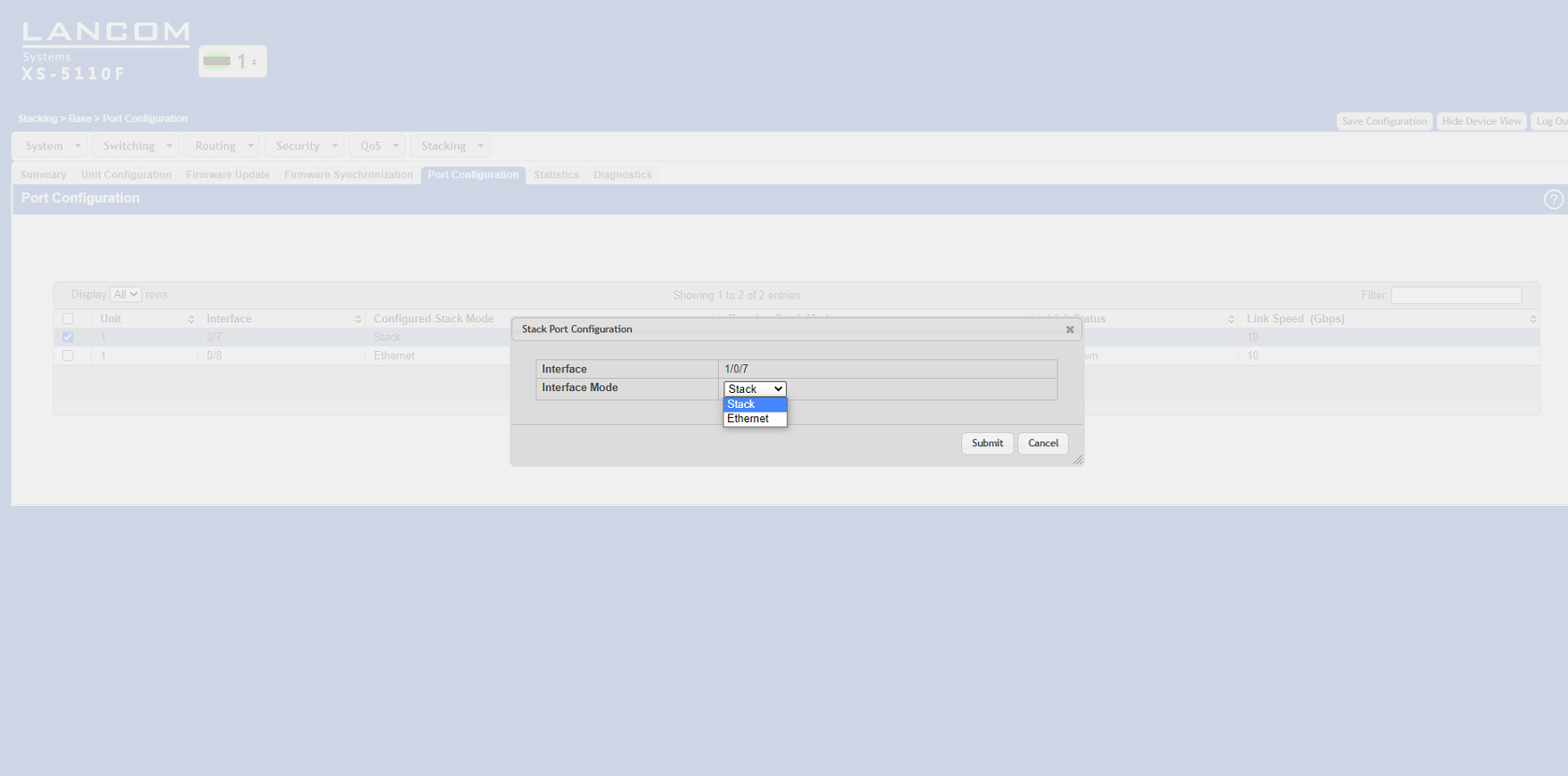
1.4 Click the Save Configuration button (in the upper right corner of the configuration window). This saves the configuration to boot-persistent memory in the switch.

1.5 Repeat these configuration steps for each of the switches.
1.6 When all of the switches in the stack have been configured, they all have to be restarted (in the menu System → Utilities → System Reboot).
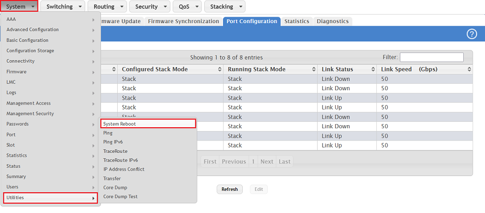
1.7 After successful configuration, the stacking status is displayed in the configuration.
1.8) Switch off all switches that have stacking configured on them and continue with the second step.
Step 2: Connect the cables and start the switches
2.1) Connect all of the switches involved in the stack using the ports configured in step 1.
2.2) First power up the switch that is to operate as the stack master/manager and then all of the other switches in the stack.
- It can take up to 2 minutes for the entire stack to become operational.
- If you start the switches in the sequence specified, the switch that was started first operates as the stack master/manager.
Useful hints:
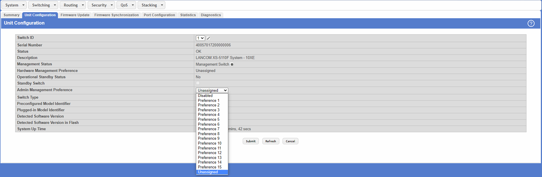
1) Manually set the stack master/manager:
You can decide which stack member is master by means of the “Admin Management Preference” in the menu Stacking → Base → Unit Configuration.
Unit preference for admin management:
- When selecting or re-selecting a stacking master/manager, the unit with the highest value set for the Admin Management Preference (Preference 15) becomes the stack master. If the preference is set to Disabled, the unit will not be selected as master.
- If the stack contains multiple members with the highest preference value, the switch with the highest MAC address becomes the stack master/manager.
2) Information on changing the stack master/manager:
The following events result in a change of the stack master/manager:
- The previous stack master/manager is removed from the stack
- The previous stack master/manager is reset or switched off
- The previous stack master/manager has failed
- The number of switch stacks is increased by adding switched-on standalone switches or switch stacks
- In the case that the stack master/manager is re-selected, the new stack master/manager becomes available within seconds.
- If a new stack master/manager is chosen and the previous stack master/manager becomes available again, the previous device will not resume its role.
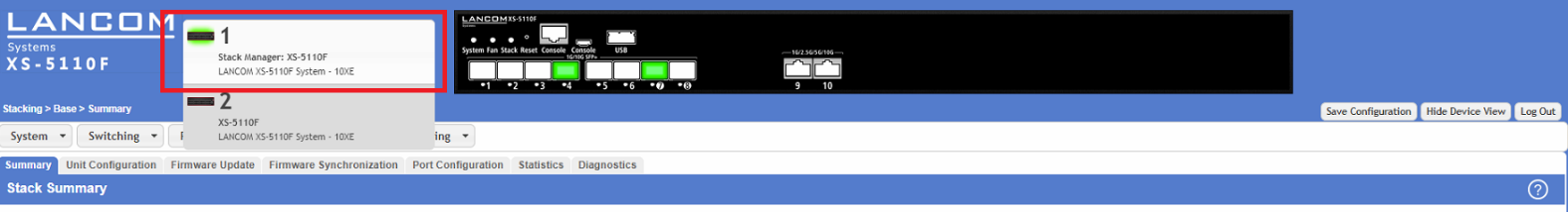
3) Viewing the stacking and port status:
3.1 The stacking status can be viewed in the menu Stacking → Base → Summary:
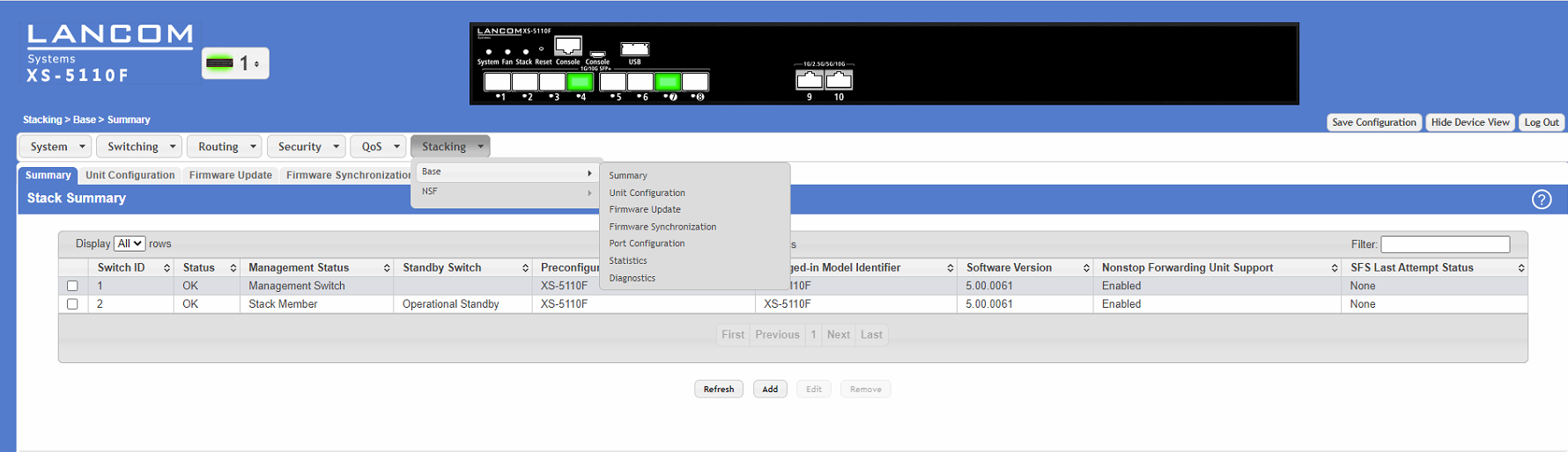
3.2 The port status on the stack members can be checked using the drop-down menu next to the LANCOM logo.