
Description:
This document describes how to set up an IKEv2 connection between the LANCOM Advanced VPN Client and a LANCOM R&S®Unified Firewall (referred to here as the United Firewall).
Requirements:
- LANCOM R&S®Unified Firewall with LCOS FX version 10.4 or later
- LANCOM Advanced VPN Client as of version 4.1
- A configured and functional Internet connection on the Unified Firewall
- Any web browser for access to the web interface of the Unified Firewall
Scenario:
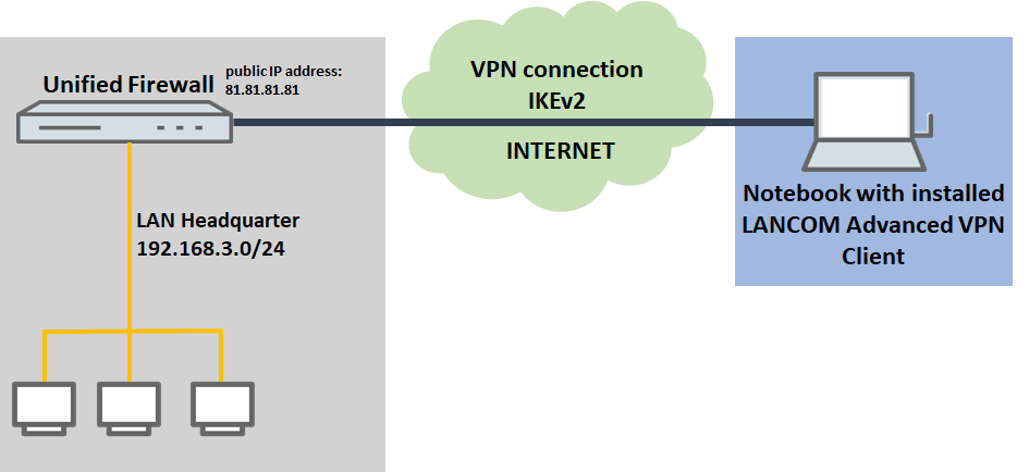
1) The Unified Firewall is connected directly to the Internet and has a public IPv4 address:
- A company wants its sales representatives to have access to the corporate network via an IKEv2 client-to-site connection.
- The notebooks used by the sales representatives have the LANCOM Advanced VPN Client installed on them.
- The company headquarters has a Unified Firewall as a gateway with an Internet connection with the fixed public IP address 81.81.81.81.
- The local network at the headquarters has the IP address range 192.168.3.0/24.
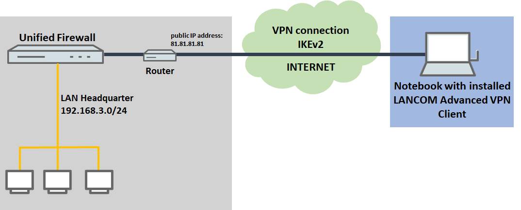
2) The Unified Firewall is connected to the Internet via an upstream router:
- A company wants its sales representatives to have access to the corporate network via an IKEv2 client-to-site connection.
- The notebooks used by the sales representatives have the LANCOM Advanced VPN Client installed on them.
- The company headquarters has a Unified Firewall as the gateway and an upstream router for the Internet connection. The router has the fixed public IP address 81.81.81.81.
- The local network at the headquarters has the IP address range 192.168.3.0/24.
Procedure:
The setup for scenarios 1 and 2 are basically the same. Scenario 2 additionally requires port and protocol forwarding to be set up on the upstream router (see section 3).
1) Configuration steps on the Unified Firewall:
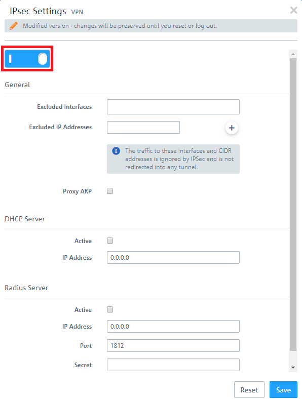
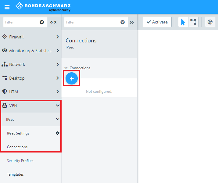
1.1) Connect to the configuration interface of the Unified Firewall and navigate to VPN → IPSec → IPSec Settings.
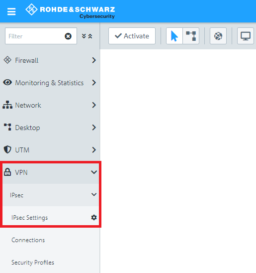
1.2) Activate IPSec.
1.3) Switch to VPN → IPSec Connections and click on the “+” icon to create a new IPSec connection.
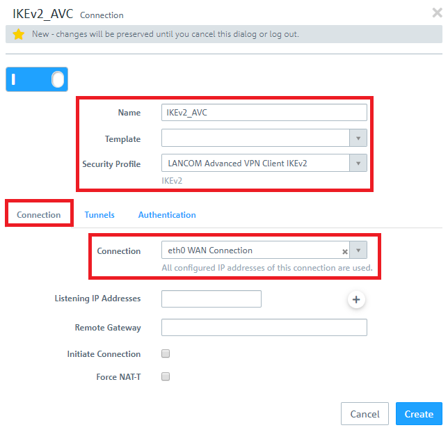
1.4) Save the following parameters:
- Name: Enter a descriptive name.
- Security Profile: Here you select the ready-made profile LANCOM Advanced VPN Client IKEv2.
- Connection: Select your configured Internet connection.
If you have created your own template or security profile , you can use these here.
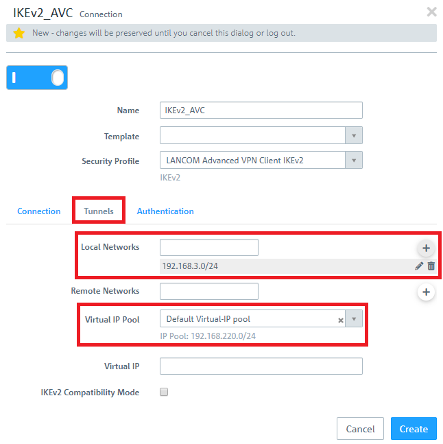
1.5) Change to the Tunnels tab and enter the following parameters:
- Local Networks: Here you enter the local networks (in CIDR notation) that the VPN client should reach. In this example, the local network at the headquarters has the IP address range 192.168.3.0/24.
- Virtual IP Pool: Select the option Default virtual IP pool. Virtual IP pools can be used to send IP address configurations to connected VPN clients.
If an IP address from a local network should be assigned to the VPN client instead of an address from the Virtual IP Pool (via the field Virtual IP), Route-based IPSec has to be activated and a routing entry for the VPN interface has to be created in the Routing Table 254 which refers to the virtual IP address in the local network.
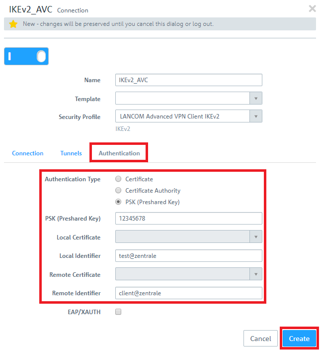
1.6) Change to the Authentication tab and enter the following parameters:
- Authentication: Select the option PSK (Preshared Key).
- PSK (Preshared Key): Set a preshared key for this connection.
- Local Identifier: Set the local identifier.
- Remote identifier: Set the remote identifier.
Due to security reasons different identities should be chosen for Local Identifier and Remote Identifier!
The Advanced VPN Client transmits the remote identity as an E-Mail address (ID_RFC822_ADDR). If the @ symbol isn't used in the remote identity, the Unified Firewall can't identify the identity type and the VPN connection can't be established. To enforce the use of the identity type E-Mail it is possible to use the string email: before the identity (e.g. email:home).
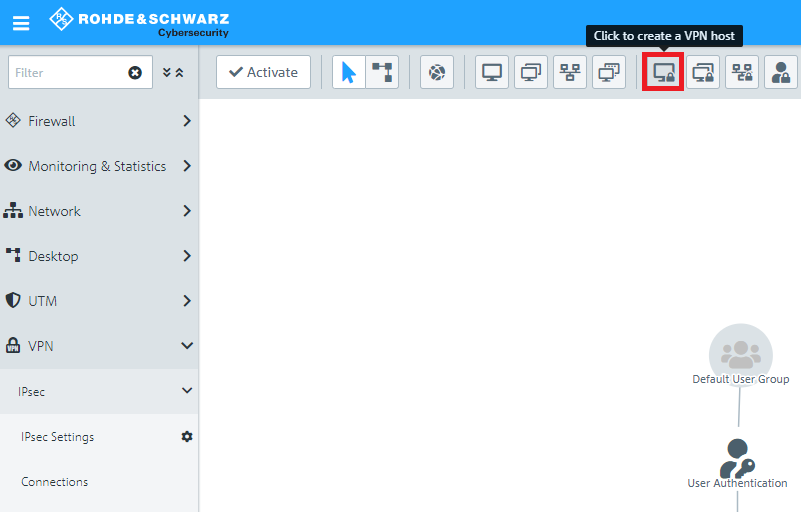
1.7) Click the icon to create a new VPN host.
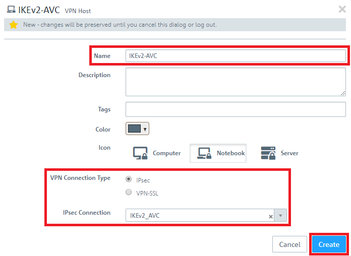
1.8) Save the following parameters:
- Name: Enter a descriptive name.
- VPN Connection Type: Select the type IPSec.
- IPSec Connection: From the drop-down menu under IPSec, select the VPN connection created in steps 1.4 - 1.6.
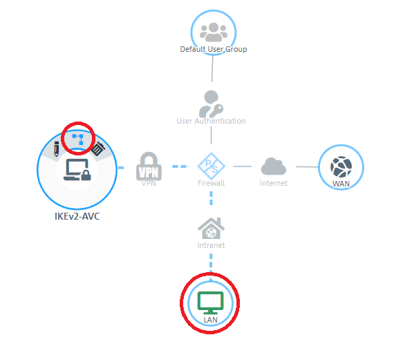
1.9) In the VPN host click on the "connection" icon and, to open the firewall objects, click on the network object that the Advanced VPN Client should access.
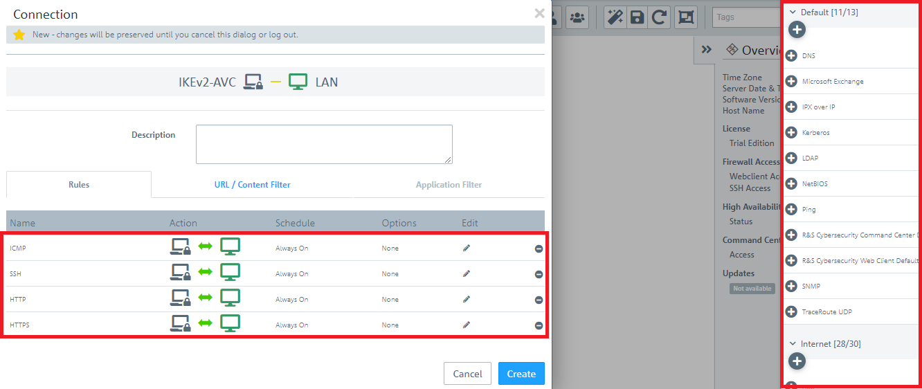
1.10) Use the “+” sign to assign the required protocols to the VPN host.
A Unified Firewall uses a deny-all strategy. You therefore have to explicitly allow communication.
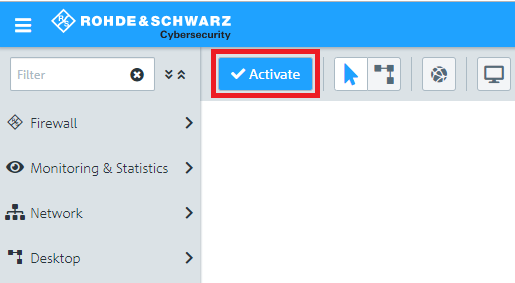
1.11) Implement the configuration changes by clicking Activate in the firewall.
1.12) Change to the menu VPN → IPsec → Connections and click on the button Export this Connection.
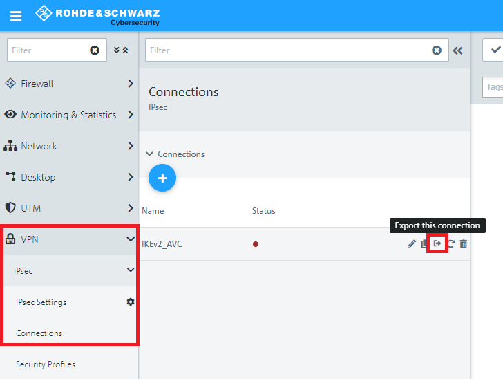
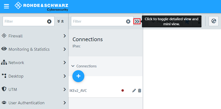
If necessary, click on the "double arrow" symbol to toggle in the detailed view where the button for profile export is located.
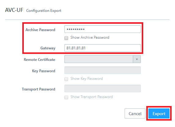
1.13) Assign an Archive Password to encrypt the exported Zip archive.
1.14) As Gateway enter the public IP address or DNS name of the Unified Firewall (in this case 81.81.81.81).
1.15) Click on Export and save the Zip file to your computer.
1.16) This concludes the configuration steps on the Unified Firewall.
2) Configuring the Advanced VPN Client:
2.1 Unpack the Zip file your exported in step 1.15 with a separate compression tool. In it you will find an *.ini file, which you can import in the LANCOM Advanced VPN Client.
The integrated compression tool in Windows does not support the Archive Password. Therefore the decompression process fails.
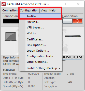
2.2) Open the Advanced VPN Client and navigate to the menu Configuration → Profiles .
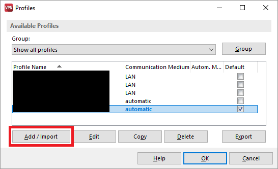
2.3) Click on Add / import to create a new VPN connection.
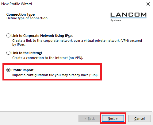
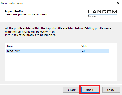
2.4) Select Profile Import.
2.5) Enter the path where you unpacked the *.ini file (see step 2.1)).
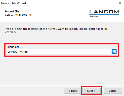
2.6) Click Next.
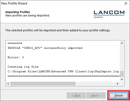
2.7) Click on Finish to finalize the file import.
2.8) Click on OK to close the Profiles menu.
2.9) The VPN client connection can now be established by clicking on the Connection switch.
3) Setting up port and protocol forwarding on a LANCOM router (scenario 2 only):
IPSec requires the use of the UDP ports 500 and 4500 as well as the protocol ESP. These must be forwarded to the Unified Firewall.
Forwarding the UDP ports 500 and 4500 automatically causes the ESP protocol to be forwarded.
If you are using a router from another manufacturer, ask them about appropriate procedure.
If the UDP ports 500 and 4500 and the ESP protocol are forwarded to the Unified Firewall, an IPSec connection to the LANCOM router can only be used if it is encapsulated in HTTPS (IPSec-over-HTTPS). Otherwise, no IPSec connection will be established.
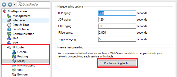
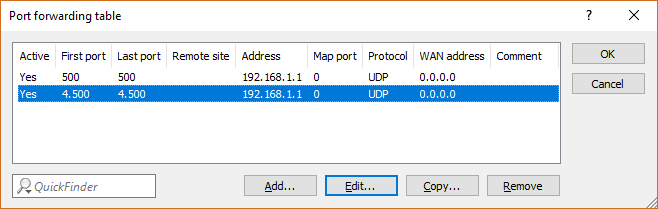
3.1) Open the configuration for the router in LANconfig and switch to the menu item IP-Router → Masq . → Port forwarding table .
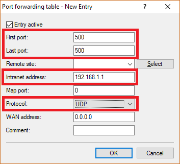
3.2) Save the following parameters:
- First port : Specify the Port 500.
- Last port : Specify the Port 500.
- Intranet address : Specify the IP address of the Unified Firewall in the transfer network between the Unified Firewall and the LANCOM router.
- Protocol: From the drop-down menu, select UDP.
3.3) Create a further entry and specify the UDP port 4500.
3.4) Write the configuration back to the router.