
Description:
If networks separated by ARF tags are to be transmitted separately over a VPN connection, each network previously had to be transmitted via an individual PPTP or L2TP tunnel, or in a separate VPN tunnel. With large numbers of branches and ARF networks, this results in a high overhead.
With the new feature HSVPN (High Scalability VPN), ARF tags used on the networks can be saved in a VPN connection as routing tags. Packets are marked with the ARF tags within the VPN tunnel and are transmitted without overhead.
Important:
- Multicast routing is not supported over HSVPN. This requires the use of a separate VPN tunnel for multicast.
- OSPF cannot be used when operating HSVPN.
- Networks can only communicate if they have been assigned the same ARF tag.
Requirements:
- LCOS as of version 10.40 (download aktuelle Version)
- LANtools as of version 10.40 (download aktuelle Version)
Scenario:
Two branches (Branch Office 1 and Branch Office 2) each establish a VPN connection to the Headquarter.
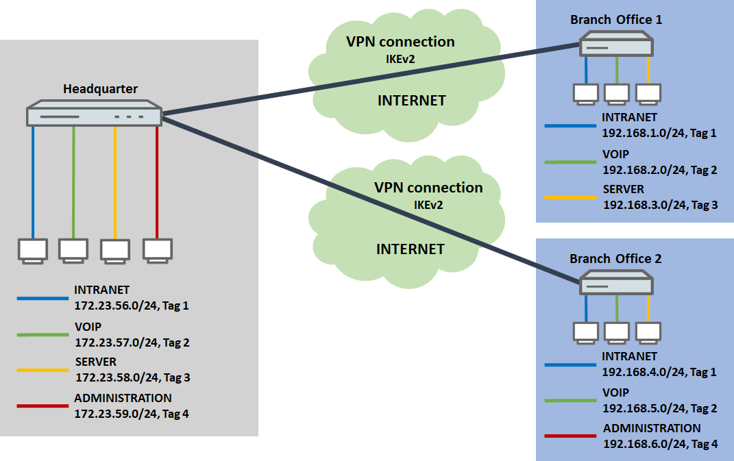
The following networks are available on the routers:
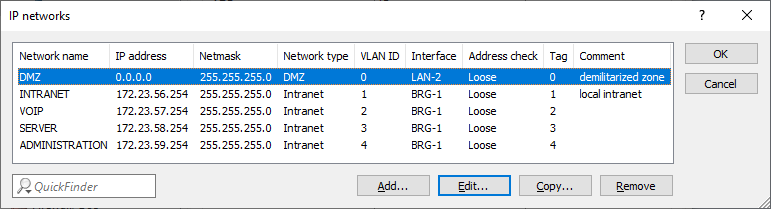
- Headquarter:
- INTRANET: 172.23.56.0/24, ARF-Tag 1
- VOIP: 172.23.57.0/24, ARF-Tag 2
- SERVER: 172.23.58.0/24, ARF-Tag 3
- ADMINISTRATION: 172.23.59.0/24, ARF-Tag 4
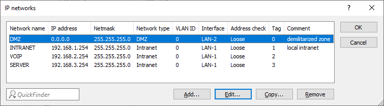
- Branch Office 1:
- INTRANET: 192.168.1.0/24, ARF-Tag 1
- VOIP: 192.168.2.0/24, ARF-Tag 2
- SERVER: 192.168.3.0/24, ARF-Tag 3
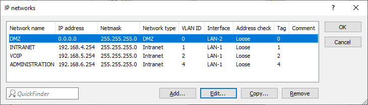
- Branch Office 2:
- INTRANET: 192.168.4.0/24, ARF-Tag 1
- VOIP: 192.168.5.0/24, ARF-Tag 2
- ADMINISTRATION: 192.168.6.0/24, ARF-Tag 4
Procedure:
1) Configuring the Headquarter:
1.1) Setting up the VPN connection:
1.1.1 Use the setup wizard to set up the IKEv2 VPN connections for Branch Office 1 and Branch Office 2 .
HSVPN only works in conjunction with an ANY-TO-ANY VPN rule that permits data traffic between any networks. The setup wizard sets up this VPN rule automatically.
1.2) Adding to the routing table:
Since configuring the VPN connection with the setup wizard creates just one VPN route, the remaining routing entries have to be created manually.
1.2.1) In LANconfig, open the configuration of the router at the Headquarter and switch to the menu item IP router → Routing → IPv4 routing table.
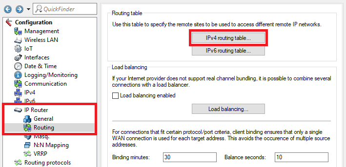
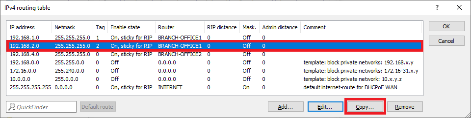
1.2.2) Select the routing entry of the VPN connection BRANCH OFFICE1 and click on Edit.
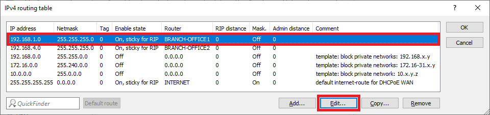
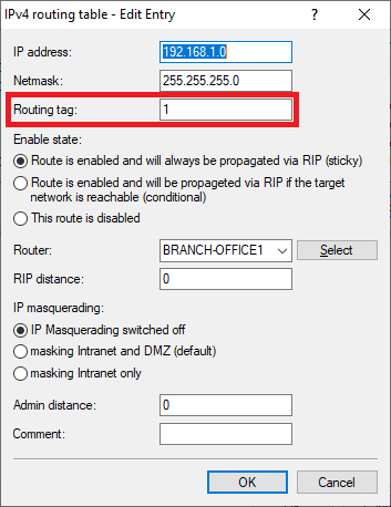
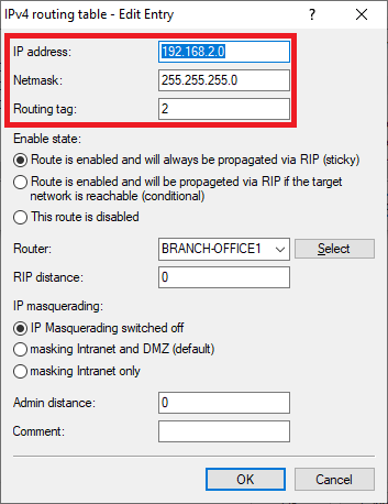
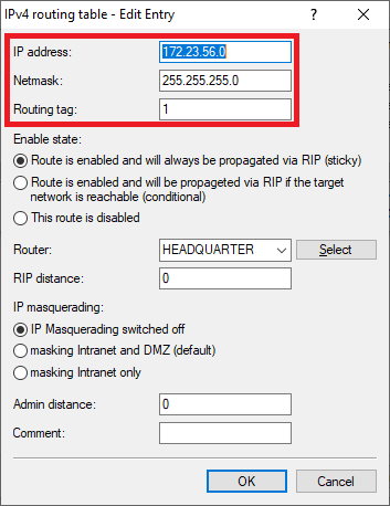
1.2.3) Enter the ARF tag used by this network at the remote site (in this example the tag 1).
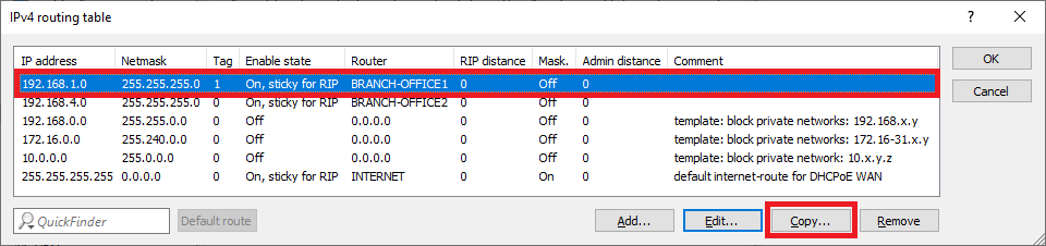
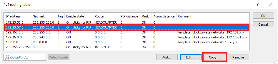
1.2.4) Mark the routing entry modified in step 1.2.3 and click on Copy.
1.2.5) Modify the following parameters:
- IP address: Enter the network address of the second network at branch office 1, to which communication is to take place via the VPN connection (in this example the network VOIP).
- Netmask: If necessary, adjust the Netmask.
- Routing tag: Enter the ARF tag that belongs to the network (in this example, tag 2).
1.2.6) Mark the routing entry modified in step 1.2.5 and click on Copy.
1.2.7) Modify the following parameters:
- IP address: Enter the network address of the third network at branch office 1, to which communication is to take place via the VPN connection (in this example the network SERVER).
- Netmask: If necessary, adjust the Netmask.
- Routing tag: Enter the ARF tag that belongs to the network (in this example, tag 3).

1.2.8) Repeat the steps 1.2.2 – 1.2.7 for the VPN connection BRANCH OFFICE2,
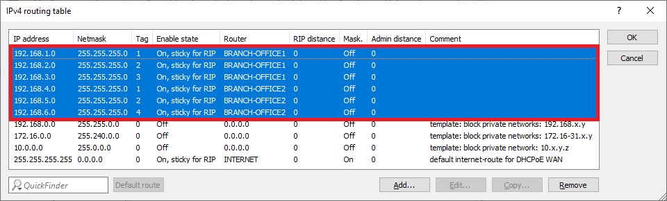
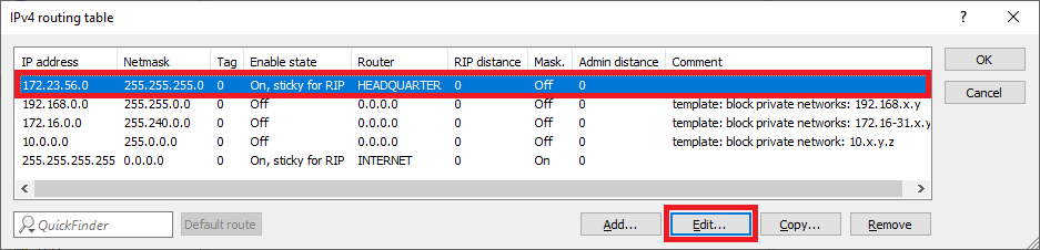
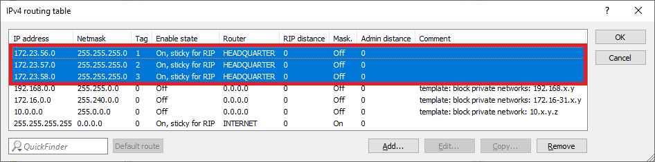
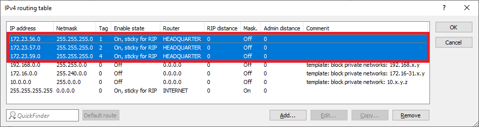
1.2.9) The IPv4 routing table should then look like this.
1.3) Setting up and assigning the HSVPN profile:
1.3.1) Switch to the menu VPN → IKEv2/IPsec → Extended settings.
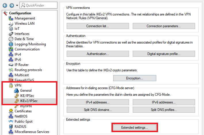
1.3.2) Switch to the menu HSVPN profiles.
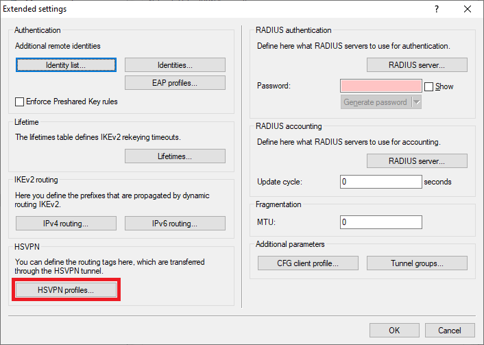
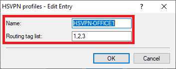
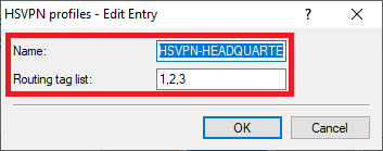
1.3.3) Create a new profile for the VPN connection BRANCH OFFICE1 and enter the following parameters:
- Name: Enter a descriptive name.
- Routing tag list: Enter the ARF tags of the networks to be transmitted via the VPN connection BRANCH OFFICE1. Multiple ARF tags can be comma separated.
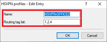
1.3.4) Create a new profile for the VPN connection BRANCH OFFICE2 and enter the following parameters:
- Name: Enter a descriptive name.
- Routing tag list : Enter the ARF tags of the networks to be transmitted via the VPN connection BRANCH OFFICE2 . Multiple ARF tags can be comma separated.
1.3.5) Navigate to the menu VPN → IKEv2/IPsec → Connection list.
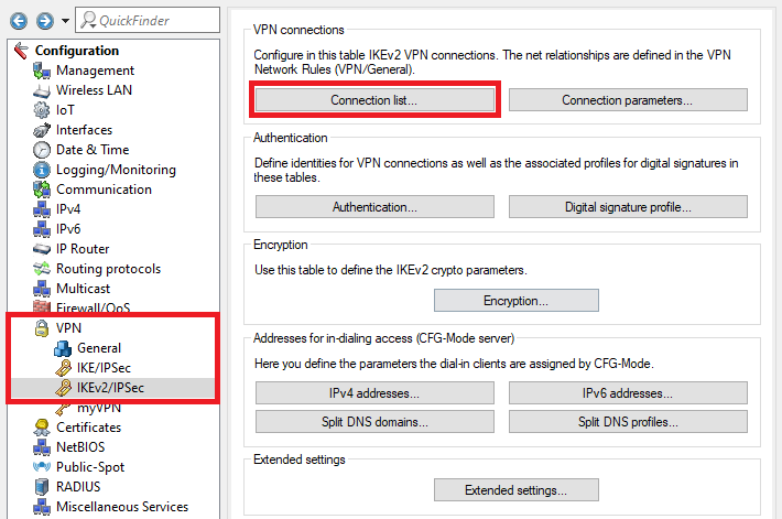
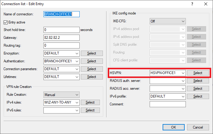
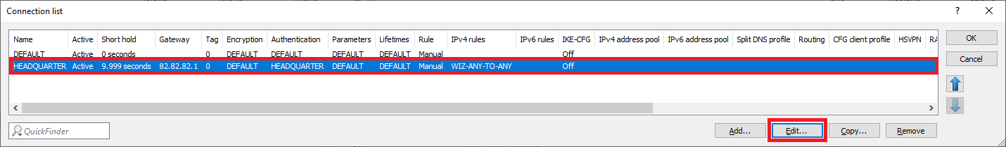
1.3.6) Select the VPN connection BRANCH OFFICE1 and click on Edit.
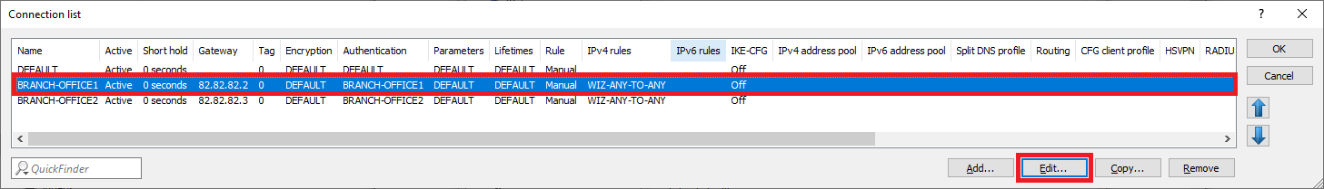
1.3.7) For HSVPN, use the drop-down menu to select the HSVPN profile created for the BRANCH OFFICE1 in Step 1.3.3.
1.3.8) Select the VPN connection BRANCH OFFICE2 and click on Edit.
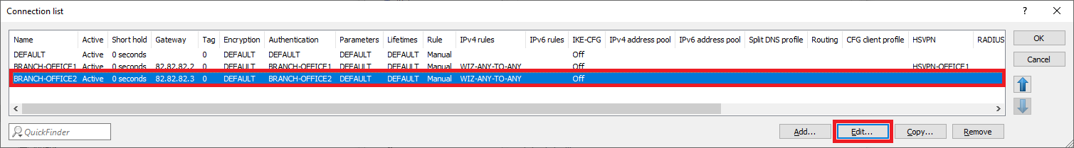
1.3.9) For HSVPN, use the drop-down menu to select the HSVPN profile created for the BRANCH OFFICE2 in Step 1.3.4.

1.3.10) This concludes the configuration at the headquarter. Write the configuration back to the router.
2) Configuring Branch Office 1:
2.1) Setting up the VPN connection:
2.1.1) Use the setup wizard to set up the IKEv2 VPN connection to the headquarter .
HSVPN only works in conjunction with an ANY-TO-ANY VPN rule that permits data traffic between any networks. The setup wizard sets up this VPN rule automatically.
2.2) Adding to the routing table:
Since configuring the VPN connection with the setup wizard creates just one VPN route, the remaining routing entries have to be created manually.
2.2.1) In LANconfig, open the configuration of the router at the branch office 1 and switch to the menu item IP router → Routing → IPv4 routing table.
2.2.2) Select the routing entry of the VPN connection HEADQUARTER and click on Edit.
2.2.3) Enter the ARF tag used by this network at the remote site (in this example the tag 1).
2.2.4) Mark the routing entry modified in step 2.2.3 and click on Copy.

2.2.5) Modify the following parameters:
- IP address: Enter the network address of the second network at Headquarters, to which communication is to take place via the VPN connection (in this example the network VOIP).
- Netmask: If necessary, adjust the Netmask.
- Routing tag: Enter the ARF tag that belongs to the network (in this example, tag 2).

2.2.6) Select the routing entry modified in step 2.2.5 and click on Copy.
2.2.7) Modify the following parameters:
- IP address: Enter the network address of the third network at Headquarter, to which communication is to take place via the VPN connection (in this example the network SERVER).
- Netmask: If necessary, adjust the Netmask.
- Routing tag: Enter the ARF tag that belongs to the network (in this example, tag 3).

2.2.8) The IPv4 routing table should then look like this.
2.3) Setting up and assigning the HSVPN profile:
2.3.1) Switch to the menu VPN → IKEv2/IPsec → Extended settings.
2.3.2) Switch to the menu HSVPN profiles.
2.3.3) Create a new profile and enter the following parameters:
- Name: Enter a descriptive name.
- Routing tag list : Enter the ARF tags of the networks to be transmitted via the VPN connection HEADQUARTER . Multiple ARF tags can be comma separated
2.3.4) Navigate to the menu VPN → IKEv2/IPsec → Connection list.
2.3.5) Select the VPN connection HEADQUARTER and click on Edit.
2.3.6) For HSVPN, use the drop-down menu to select the HSVPN profile created in Step 2.3.3.

2.3.7) This concludes the configuration at the branch office 1. Write the configuration back to the router.
3) Configuring Branch Office 2:
3.1) Setting up the VPN connection:
3.1.1) use the setup wizard to set up the IKEv2 VPN connection to the headqarter .
HSVPN only works in conjunction with an ANY-TO-ANY VPN rule that permits data traffic between any networks. The setup wizard sets up this VPN rule automatically.
3.2) Adding to the routing table:
Since configuring the VPN connection with the setup wizard creates just one VPN route, the remaining routing entries have to be created manually.
3.2.1) In LANconfig, open the configuration of the router at the branch office 2 and switch to the menu item IP router → Routing → IPv4 routing table.
3.2.2) Select the routing entry of the VPN connection HEADQUARTER and click on Edit.
3.2.3) Enter the ARF tag used by this network at the remote site (in this example tag 1).
3.2.4) Select the routing entry modified in step 3.2.3 and click on Copy.
3.2.5) Modify the following parameters:
- IP address: Enter the network address of the second network at Headquarter, to which communication is to take place via the VPN connection (in this example the network VOIP).
- Netmask: If necessary, adjust the Netmask.
- Routing tag: Enter the ARF tag that belongs to the network (in this example, tag 2).
3.2.6) Mark the routing entry modified in step 3.2.5 and click on Copy.
3.2.7) Modify the following parameters:
- IP address: Enter the network address of the fourth network at the Headquarter, to which communication is to take place via the VPN connection (in this example the network ADMINISTRATION).
- Netmask: If necessary, adjust the Netmask.
- Routing tag: Enter the ARF tag that belongs to the network (in this example, tag 4).

3.2.8) The IPv4 routing table should then look like this.
3.3) Setting up and assigning the HSVPN profile:
3.3.1) Switch to the menu VPN → IKEv2/IPsec → Extended settings.
3.3.2) Switch to the menu HSVPN profiles.
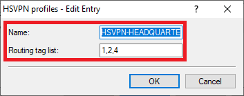
3.3.3) Create a new profile and enter the following parameters:
- Name: Enter a descriptive name.
- Routing tag list : Enter the ARF tags of the networks to be transmitted via the VPN connection HEADQUARTER . Multiple ARF tags can be comma separated.
3.3.4) Navigate to the menu VPN → IKEv2/IPsec → Connection list.
3.3.5) Select the VPN connection HEADQUARTER and click on Edit.
3.3.6) For HSVPN, use the drop-down menu to select the HSVPN profile created in Step 3.3.3.
3.3.7) This concludes the configuration at the branch office 2. Write the configuration back to the router.