Description:
This document describes how to configure a wireless network supported by multiple LANCOM access points, where guest users have to enter their user credentials at the central gateway in order to communicate with the Internet (Public Spot).
Scenario: - After logging in to the Public Spot via the LAN and/or WLAN, guests should be able to communicate with the Internet.
- Employees should be able to use the LAN and/or WLAN to communicate with the Internet and intranet without having to login.
- No communication is allowed between the guest and company networks.
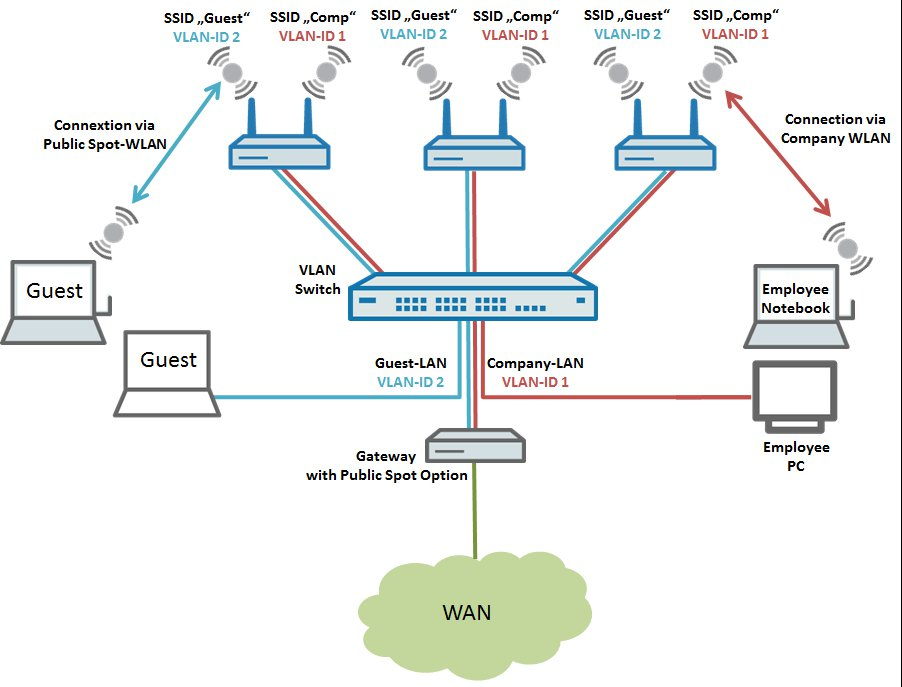 Image showing a complex network configuration interface with labels like SSID, VLAN ID, and connection types for different network segments including GuestLAN and CompanyLAN.
The following steps describe how to configure the central LANCOM gateway with its Public Spot option, and also the configuration of the LANCOM switch and a LANCOM access point. To operate more than one LANCOM access point, the steps taken for the configuration can be repeated for any number of APs.
Procedure:
1) Configuring the local networks and VLANs on the gateway router:
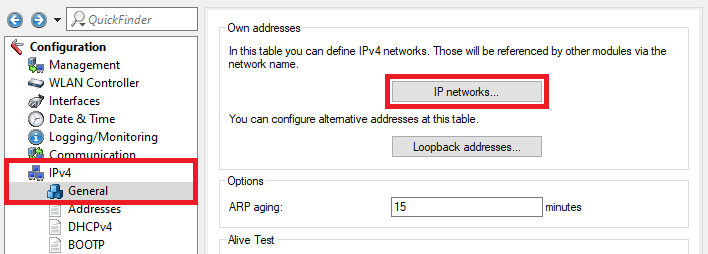
1.1) Open the configuration of the gateway router in LANconfig and go to the menu IPv4 → General → IP networks.
 Screenshot of a technical configuration interface for managing IPv networks, displaying options for network names, alternative addresses, and various network settings including ARP aging and DHCP.
1.2) In the IP networks dialog, click the Add button to create a new network.
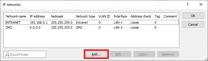 Image of a complex technical interface displaying various network configurations and settings with partially obscured text.
1.3) Change the following parameters for the GUEST network:
- Network name: Enter a descriptive name for the guest network (in this case GUEST).
- IP address: Enter an IP address from an IP address range which is not already in use.
- Netmask: Enter the subnet mask which is associated with the IP address.
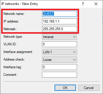 Image displaying a partial view of a technical user interface or configuration menu with fragmented text and unclear settings.
1.4) The table IP networks has to appear as follows afterwards:
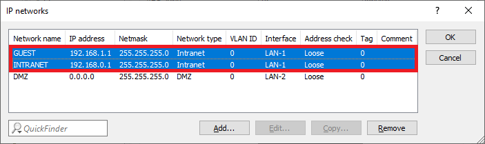 Image of a network configuration interface displaying network names, IP addresses, netmasks, network types, VLAN IDs, and interface addresses, with options to add, edit, copy, and remove entries.
1.5) Go to the menu IPv4 → DHCPv4 → DHCP networks.
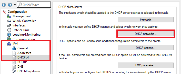 Image showing a DHCP client configuration interface with various settings, including management, SW/LAN Controller, Date/Time, General DHCP options, and DNS parameters, for network configuration and management.
1.6) Click Add to enter a new entry in the table DHCP networks.
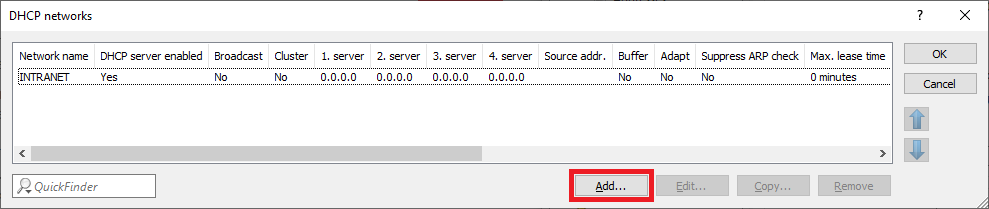 Image of a digital interface displaying DHCP network configurations, with additional settings or options labeled SSS.
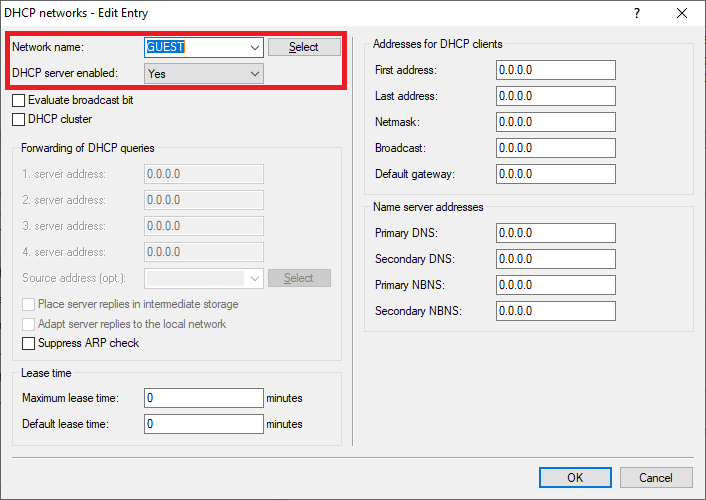
1.7) Edit the following parameters:
- Network name: In the dropdown menu select the network created in step 1.3) (in this example the network GUEST).
- DHCP server enabled: In the dropdown menu select Yes to activate the DHCP server.
 An image showing a complex configuration menu for network settings, featuring options such as DHCP networks editing, source address selection, and ARP suppression controls.
1.8) The table DHCP networks has to appear as follows afterwards:
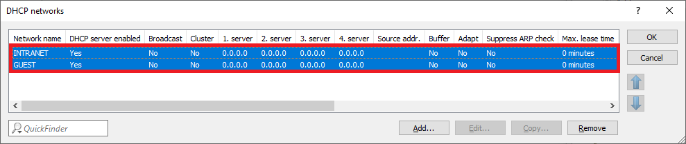 Image of a computer network configuration interface showing DHCP network settings, server enable broadcast options, and ARP check settings.
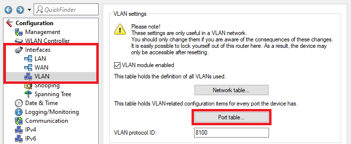
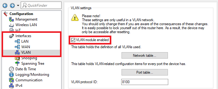
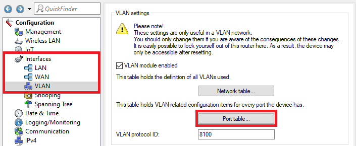
1.9) Go to the menu Interfaces → VLAN and activate the VLAN module.
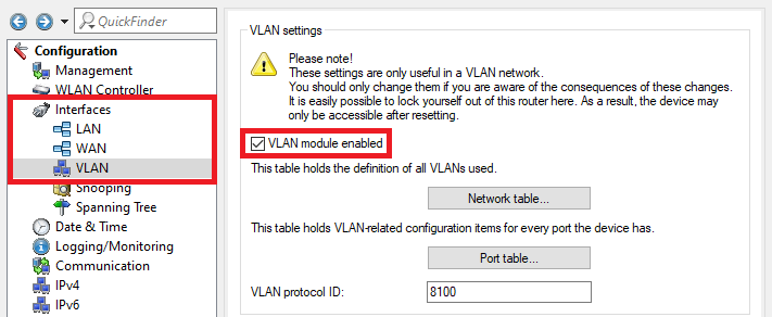 Screenshot of a network device's VLAN settings configuration menu displaying options for management, control, spanning tree, and logging, with warnings about the implications of changes.
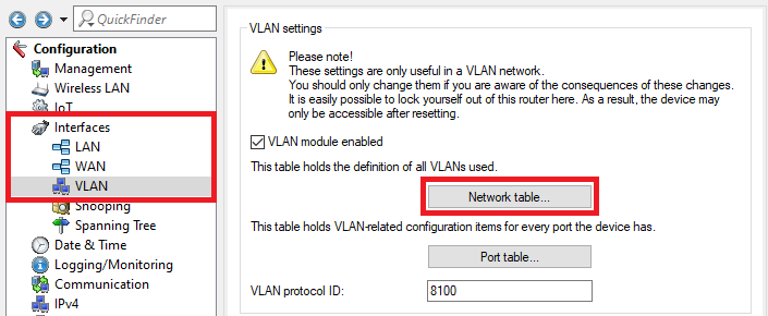
1.10) Go to the menu Network table.
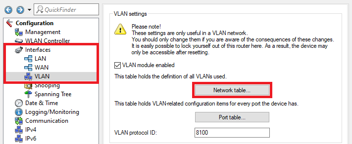 Screenshot showing the VLAN settings configuration menu in a network management interface, outlining options for VLAN management, WLAN control, BLWAN enabling, and detailed VLAN-related configurations for ports.
1.11) Select the entry Default_VLAN and click on the Edit button.
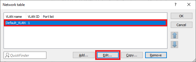 A screenshot of a user interface featuring the label 'Networktable x'.
1.12) Click on the Select button next to Port list to select the interface LAN-1.
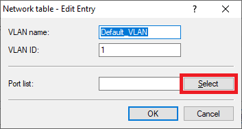 Image showing a partially visible user interface with the words 'vaio', 'rotia', and 'Coe' displayed, possibly related to a technical configuration menu.
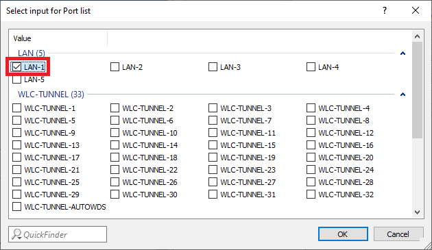 Screenshot of a technical user interface displaying a selection input for a port list, with various port names and configuration options listed in a complex format.
1.13) Create a new entry and change the following parameters:
- VLAN name: Enter a descriptive name for the VLAN (in this example GUEST).
- VLAN ID: Enter the VLAN ID 2.
- Port list: Select the locial interface LAN-1.
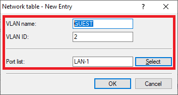 Image displaying a partial view of a technical user interface with the fragmented text labels 'arene', 'aio', 'atta', and 'Coe'.
1.14) The Network table has to appear as follows afterwards:
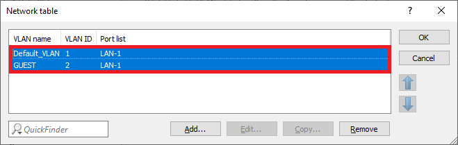 Image of a network configuration interface with options for default WAN, LAN settings, and controls to copy or remove network items.
1.15) Go to the menu Port table.
 An image of a complex network interface configuration menu displaying VLAN settings, management options, and VLAN-related configuration items, warning about changes that may lock the user out of the router.
1.16) Select the VLAN port LAN-1: Local area network 1 and click Edit.
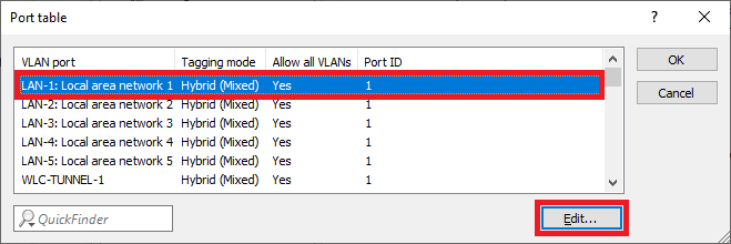 Diagram displaying various LAN configurations with hybrid and mixed network settings labeled as 'Local Area Network'.
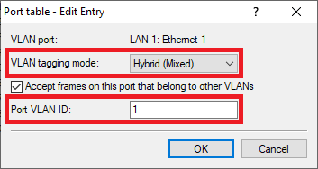
1.17) Change the following parameters:
- VLAN tagging mode: Make sure that the tagging mode Hybrid (Mixed) is selected.
- Port VLAN ID: Make sure that the VLAN ID 1 is used.
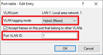 Screenshot of a network configuration interface showing options to accept frames on a port that belong to other VLANs, with a cancel button.
1.18) Go to the menu IPv4 → General → IP networks to add the VLAN IDs to the networks.
Screen capture of a network configuration interface showing options to define IPv4 networks, manage DNS settings, and configure alternative addresses. 1.19) Select the network INTRANET and click Edit.
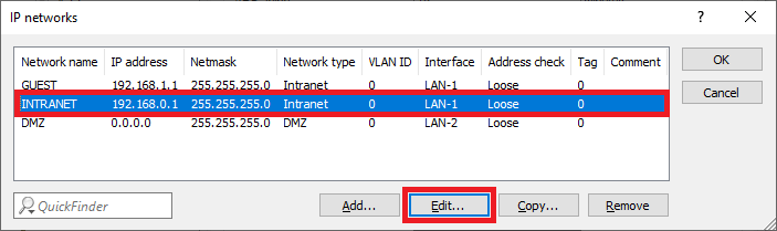 Image displaying a partial view of a technical configuration interface with blurred network settings and parameters such as IP network details, netmask, and interface address.
1.20) Enter the VLAN-ID 1 since it belongs to the company network (INTRANET).
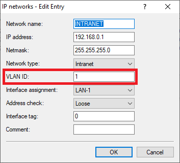 Image of a partial, unclear text possibly related to a sewer system interface or configuration screen, with distorted or obscured words.
1.21) Edit the network GUEST and change the following parameters:
- VLAN ID: Enter the VLAN ID 2.
- Interface tag: Enter an Interface tag unequal 0, so that the communication between the network GUEST and the network INTRANET is prevented (in this example the tag 1 is used).
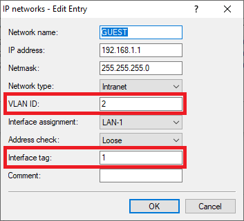 Image showing a partial view of a user interface menu with text options including 'Newer', 'Paseo', 'Nena', and 'Commer Cd'.
1.22) The table IP networks has to appear as follows afterwards:
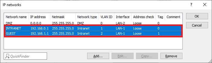 Image displaying a network configuration interface with labeled fields including network name, IP address, netmask, network type, and interface address, along with options for checking connections and tags with comments labeled OK.
1.23) The network and VLAN configuration is complete. Write the configuration back into the router.
2) Configuring the Public Spot and the RADIUS server on the gateway router
2.1) Go to the menu Public-Spot → Authentication and select the mode Authenticate with name and password.
 Image depicting a technical configuration interface or menu with various authentication and communication settings, such as login methods, encryption standards, and router protocols.
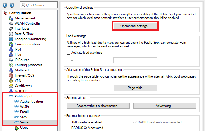
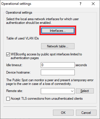
2.2) Go to the menu Public Spot → Server → Operational settings.
 Screenshot of a technical configuration menu for managing public spot settings, including access, networking interfaces, user authentication, load warnings, and routing protocols.
2.3) Go to the menu Interfaces.
 Screenshot of a technical configuration interface displaying various operational settings and security options.
2.4) Select the Interface for the Public Spot authentication (in this example the interface LAN-1), and click Edit.
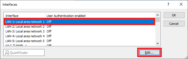 Image showing a blurry or unclear screenshot of a technical user interface with partially visible and scrambled text labels.
2.5) Activate the User Authentication for the interface LAN-1: Local area network 1.
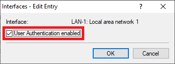 Image of a computer network configuration interface showing options for LAN settings and user authentication.
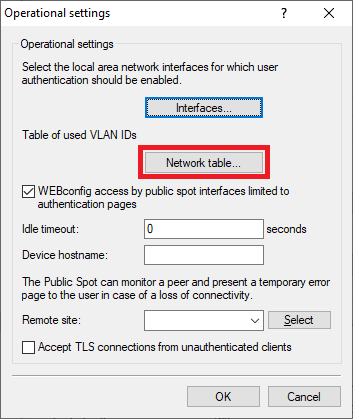
2.6) Go to the menu Network table to specify which VLAN ID should be used in conjunction with the Public Spot.
 Screenshot of a technical configuration interface displaying various operational settings including Public Spot interface limitations, TLS connections, and error monitoring options.
2.7) Click Add to create a new entry.
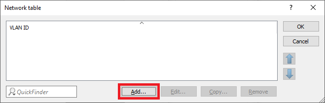 Screenshot displaying a partial user interface with the text 'Networktable x WAND Lo tT' visible, indicating a configuration or settings menu.
2.8) Select the VLAN ID 2.
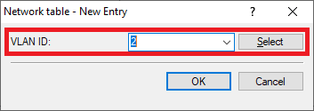 Diagram showing the geometric representation of a cone.
2.9) Go to the menu Public Spot → Users → RADIUS server to point to the integrated RADIUS server.
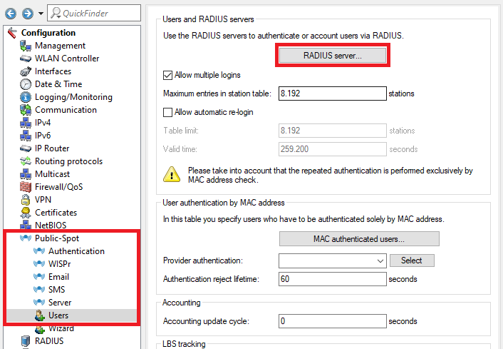 Screenshot of a technical configuration interface showing options for RADIUS server authentication, management interfaces, date and time settings, logging and monitoring controls, communication settings, routing protocols, firewall and QoS settings, and MAC address authentication specifications.
2.10) Ex factory there is an entry named LOCAL. It points to the integrated RADIUS and Accounting server.
Make sure that the following parameters are used:
- Auth. server address: 127.0.0.1
- Auth. server port: 1812
- Acc. server address: 127.0.0.1
- Acc. server port: 1813
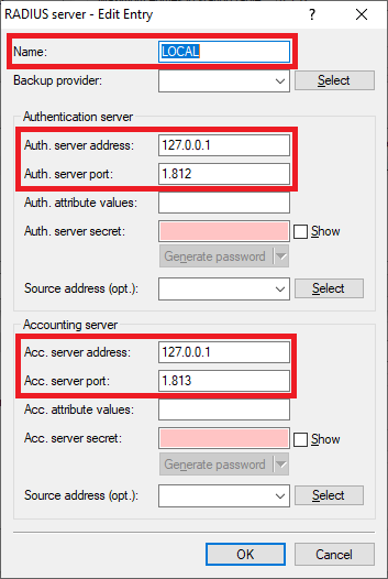 Image shows a screen displaying partial and scrambled text related to technical user interface or configuration settings, including repetitive mentions of generating passwords.
2.11) Go to the menu Public Spot → Wizard → Public Spot SSIDs.
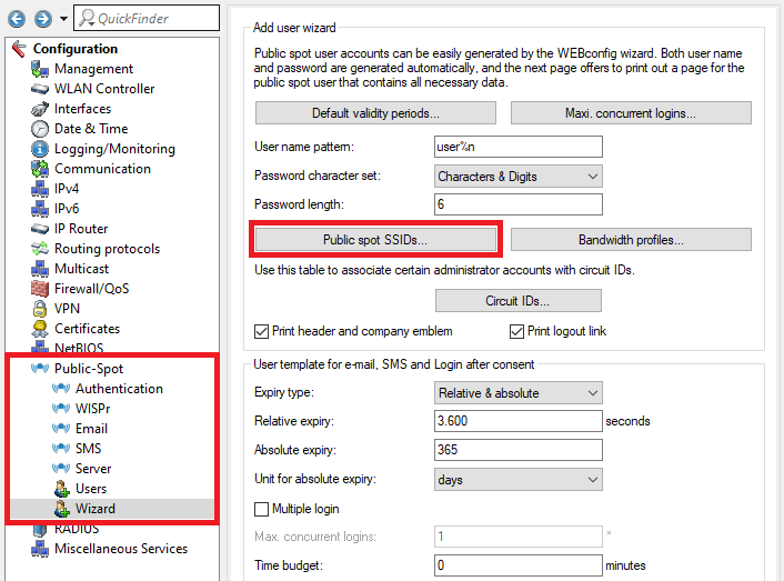 Image of a configuration interface for public spot user accounts, showing options like user and password generation, print settings, and management controls including authentication and network settings.
2.12) Create a new entry and change the following parameters:
- SSID: Enter the SSID for the guest network created in step 4.4) (in this example Guest), to print the name of the SSID on the Public Spot voucher.
- SSID selected: Set this option to Yes, in order for the SSID to be printed on the Public Spot voucher whenever a Public Spot user is created and the voucher printed via the setup wizard Create Public Spot Account.
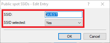 Image showing a partial view of a technical interface or configuration menu labeled 'a D Concel'.
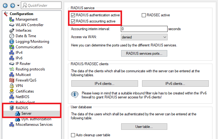
2.13) Go to the menu RADIUS → Server and activate the functions RADIUS authentication and RADIUS accounting.
 This image features a technical interface for configuring network settings, including sections for RADIUS authentication, roaming settings, WAN access rules, firewall, quality of service configurations, and various network services protocols.
2.14) Go to the menu RADIUS services ports.
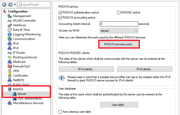 Image depicting a technical configuration interface with various network settings including RADIUS authentication, SWLANControl, firewall settings, user database configurations, and other related network services options.
2.15) Make sure that the Authentication port is set to 1812 and the Accounting port to 1813.
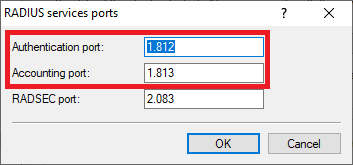 Image showing a partial view of a technical user interface related to RADIUS service settings or sports configurations.
2.16) The configuration of the Public Spot and the RADIUS server is complete. Write the configuration back into the router.
3) Configuring the VLAN on the LANCOM switch:
3.1) Open the configuration of the LANCOM switch in a web browser and go to the menu Configuration → VLAN → VLAN Membership.
3.2) In this example the switch ports should be configured as follows:
- LANCOM Access Point at Port 1
- LANCOM gateway router at Port 3
- Port 23 is used for access to the company network (192.168.0.0/24) via LAN.
- Port 24 is used for access to the guest network (192.168.1.0/24) via LAN. The authentication is controlled via the Public Spot.
3.3) Edit the existing Default VLAN and enter the name of the network (in this example COMPANY).
3.4) Add a new VLAN via the button Add New VLAN. Enter the name of the network (in this example GUEST) and enter the VLAN ID 2.
3.5) Tick the checkboxes with the Ports 1, 3 and 24 for the VLAN GUEST.
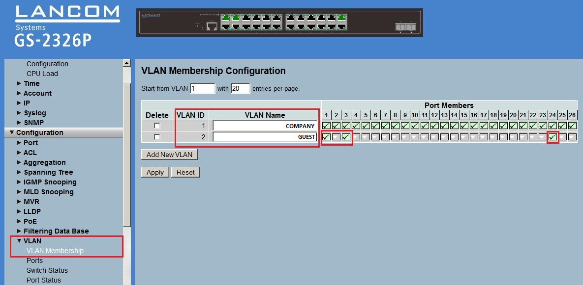 Image depicting a complex network configuration interface with various settings including CPU Load, VLAN Membership, Syslog, ACL, Aggregation, IGMP Snooping, and more displayed on a system management screen.
3.6) Go to the menu
Ports and edit the port configuration for the p
orts 1, 3, 23 and
24:
- Make sure, that the Egress Rule is set to Hybrid for the Ports 1 and 3 and that the PVID is set to 1.
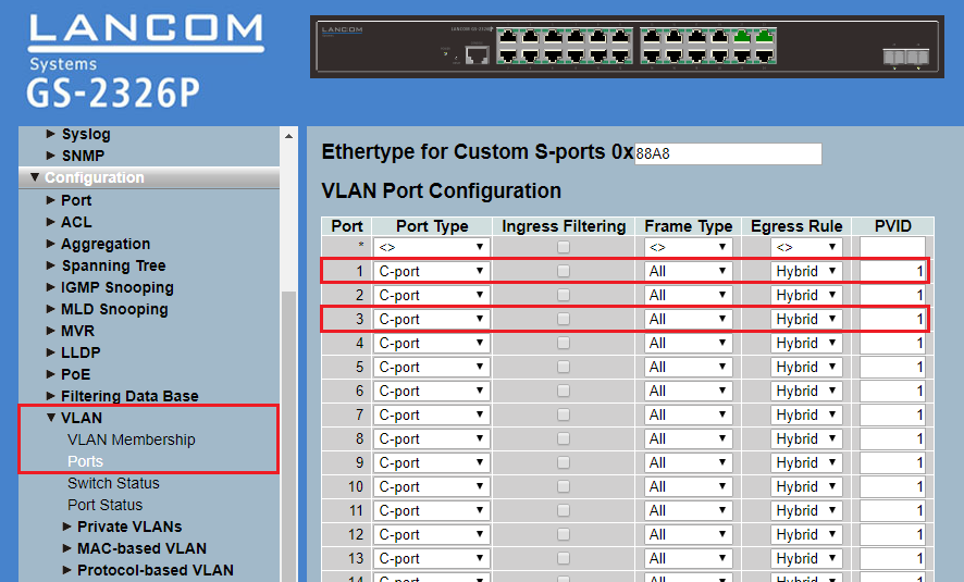 Image of a complex network configuration interface showing various settings such as Syslog, SNMP, VLAN configurations, ACL, Port Types, IGMP Snooping, and more, arranged in a structured format possibly part of a technical diagram.
 - For the Port 23 set the Egress Rule to Access and make sure, that the PVID is set to 1.
- For the Port 24 set the Egress Rule to Access and make sure, that the PVID is set to 2.
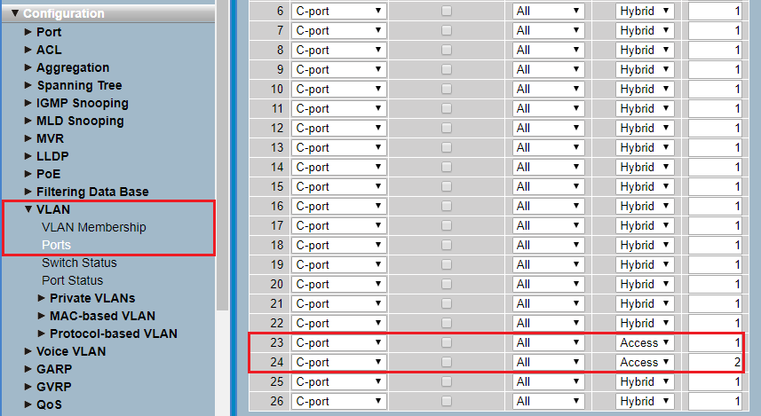 Image showing a network configuration interface with various settings such as VLAN memberships, spanning tree protocols, IGMP and MLD snooping, and port statuses among others.
3.7) The VLAN configuration of the switch is complete. Write the configuration back into the device.
4) Configuring a LANCOM access point
4.1) Go to the menu IPv4 → General → IP networks.
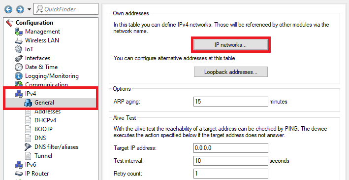 Alt Description: Screenshot of a network configuration interface detailing options for defining IPv network settings, alternative addresses, logging, monitoring, and connectivity tests such as PING for target IP address verification.
4.2) Assign an IP address from the company network to the Access Point (in this example the network 192.168.0.0/24) and enter the VLAN ID 1.
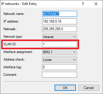 Image of a blurry or partially obscured technical diagram possibly related to sewer system configurations.
4.3) Go to the menu Wireless-LAN → General → Logical WLAN settings.
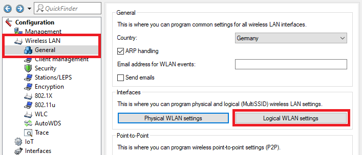 Image of a user interface for programming wireless LAN settings, featuring options for general ARP handling, security enhancements, station LEDs, encryption, and Multi-SSID configurations.
4.4) Create a WLAN for the company network and the guest network for each radio module and edit the encryption parameters.
WLAN interface 1 - Network 1:
Network tab:
- Make sure, that the checkbox WLAN network enabled is ticked.
- Enter a descriptive name for the SSID (in this example the name Comp).
Encryption tab:
- Enter a WPA key for Key 1/passphrase. It has to be entered in WLAN devices to be able to connect to the WLAN.
 An image displaying a detailed WLAN settings interface with options for network enabling, SSID broadcast, MAC filtering, client bridge support, bandwidth control, RADIUS accounting, and additional network management features.
 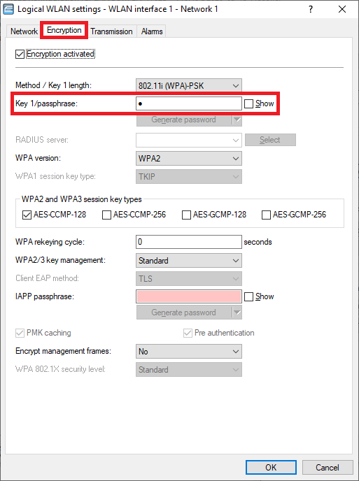 The image displays a WLAN settings interface with options for encryption types, key length, and RADIUS server configuration, along with a generate password feature.
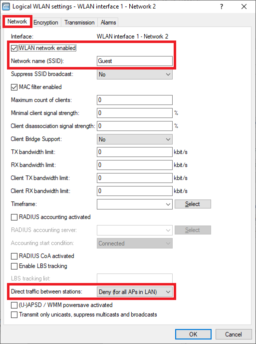
WLAN interface 1 - Network 2:
Network tab:
- Make sure, that the checkbox WLAN network enabled is ticked.
- Enter a descriptive name for the SSID (in this example the name Guest).
Encryption tab:
- Deactivate the encryption. WLAN devices should authenticate themselves at the Public Spot via login credentials.
 Screenshot of a network configuration interface showing WLAN settings such as SSID broadcast suppression, MAC filter activation, client bridge support, and various bandwidth controls.
  Image displaying a user interface with various WLAN security settings, highlighting options such as WPA2, WPA3, AES-CCMP encryption modes, PSK authentication, and key management features.
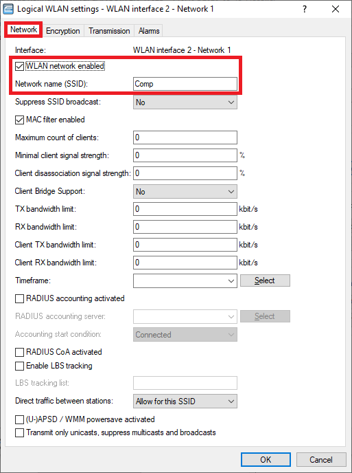
WLAN-Interface 2 - Netzwerk 1:
Network tab:
- Make sure, that the checkbox WLAN network enabled is ticked.
- Enter a descriptive name for the SSID (in this example the name Comp).
Encryption tab:
- Enter the same WPA key for Key 1/passphrase you used for the interface WLAN interface 1 - Network 1.
 Screenshot of a network configuration interface showing various WLAN settings including options for SSID broadcast, MAC filter, Client Bridge Support, RADIUS accounting, and power saving options.
 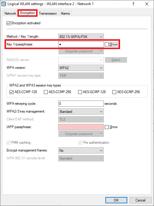 The image displays a technical configuration menu for WLAN settings, including options for encryption methods, key length, RADIUS server, and AES/CCMP encryption types.
WLAN interface 2 - Netzwerk 2:
Network tab:
- Make sure, that the checkbox WLAN network enabled is ticked.
- Enter a descriptive name for the SSID (in this example the name Guest).
Encryption tab:
- Deactivate the encryption. WLAN devices should authenticate themselves at the Public Spot via login credentials.
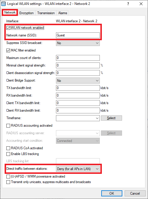 Image of a network settings interface showing options such as WLAN settings, MAC filter activation, SSID broadcast suppression, and RADIUS accounting configurations.
 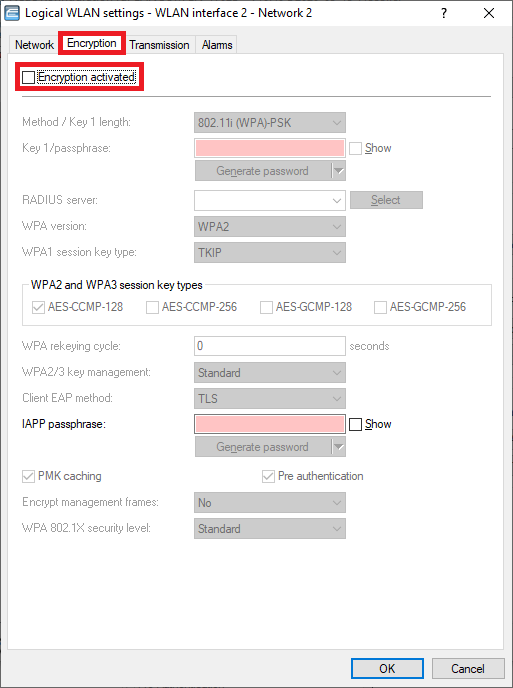 Image of a technical configuration menu for WLAN settings displaying various security protocols and encryption types such as WPA2, WPA3, AES-CCMP, and options for key regeneration and pre-authentication.
4.5) Go to the menu Interfaces → VLAN and activate the VLAN module.
 A screenshot of a technical configuration interface showing various settings, including VLAN configurations and Spanning Tree protocols, with warnings about the consequences of changes.
4.6) Go to the menu Network table.
 Screenshot of a technical configuration interface showing settings for VLANs, spanning tree protocols, and other network-related options, with a caution message about understanding the consequences of changes.
4.7) Select the entry Default_VLAN and click Edit.
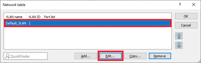 Image showing a part of a technical user interface labeled 'Networktable x E'.
4.8) In the Port list click Select to add the logical interfaces for the company network.
 Close-up view of a user interface displaying the menu options 'van Pott Care.'
4.9) Select all logical interfaces, which should communicate via the company network (in this example the interfaces LAN-1, WLAN-1 and WLAN-2).
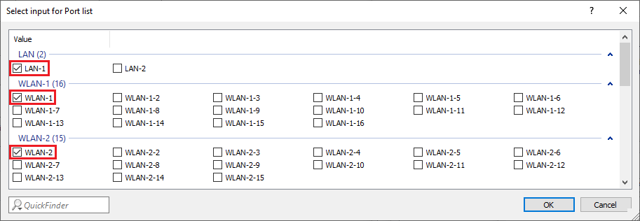 Image displaying a configuration menu with selection options for different port lists including LAN, WLAN, and various named configurations with options like Oman, Omans, Owane, among others.
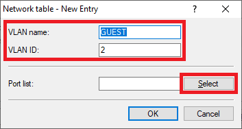
4.10) Create a new entry and enter the following parameters:
- VLAN name: Enter a descriptive name for this VLAN (in this example GUEST).
- VLAN ID: Enter the VLAN ID 2.
- Afterwards click on Select in the Port list to add the logical interfaces for the guest network .
 Interface screen display labeled 'Latina a Potts cone', possibly representing settings or diagnostic tools.
4.11) Select all logical interfaces, which should communicate via the guest network (in this example the interfaces LAN-1, WLAN-1-2 and WLAN-2-2).
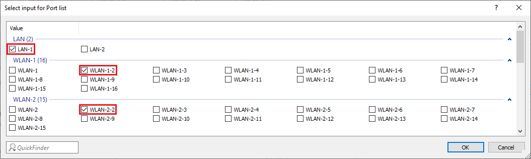 Image displaying a technical configuration menu for selecting port lists with options including LAN and WLAN, accompanied by various unclear or partially visible names and settings.
4.12) The Network table has to appear as follows afterwards:
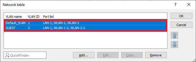 Screenshot of a network configuration interface displaying settings for WAN, VLAN ID, and ports with options to modify or remove configurations.
4.13) Go to the menu Port table.
 Screenshot of a complex technical configuration interface displaying settings for VLAN, Spanning Tree Protocol, and other network parameters, warning about potential consequences of changes.
4.14) Edit the individual logical interfaces as follows:
LAN-1:
- VLAN tagging mode: Make sure, that the tagging mode Hybrid (Mixed) is used.
- Port VLAN ID: Make sure, that the Port VLAN ID 1 is used.
 Screenshot of a network configuration menu option to accept frames on a port that belong to other VLANs with the cancel button visible.
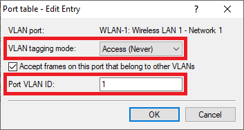
WLAN-1:
- VLAN tagging mode: In the dropdown menu select the tagging mode Access (Never).
- Port VLAN ID: Make sure, that the Port VLAN ID 1 is used.
WLAN-2:
- VLAN tagging mode: In the dropdown menu select the tagging mode Access (Never).
- Port VLAN ID: Make sure, that the Port VLAN ID 1 is used.
 Screenshot of a configuration menu with options to accept frames from other VLANs on a specific port, alongside a cancel button.
  Screenshot of a network configuration menu showing options to accept frames on a port that belong to other VLANs, with a cancel button visible.
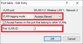
WLAN-1-2:
- VLAN tagging mode: In the dropdown menu select the tagging mode Access (Never).
- Port VLAN ID: Enter the Port VLAN ID 2.
WLAN-2-2:
- VLAN tagging mode: In the dropdown menu select the tagging mode Access (Never).
- Port VLAN ID: Enter the Port VLAN ID 2.
 An image of a configuration menu with options related to VLAN settings, including a selectable option to accept frames on a port from other VLANs and a cancel button.
  Screenshot of a network configuration interface with options to accept frames from other VLANs on a specific port, featuring a Cancel button.
4.15) The Port table has to appear as follows afterwards:
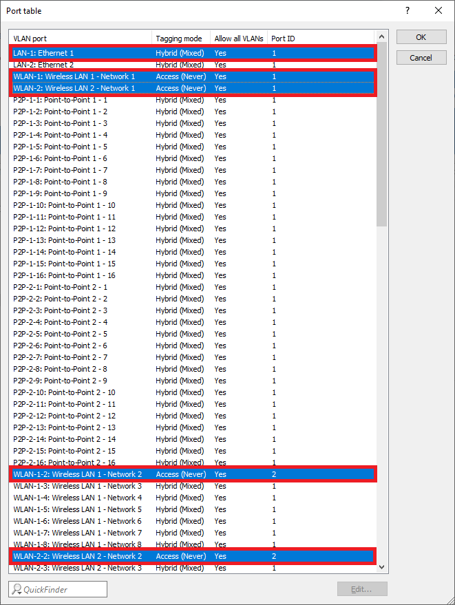 Screenshot of a network configuration interface displaying various settings for VLAN port tagging, hybrid modes, and wireless LAN network access options with mixed permissions.
4.16) The configuration of the access point is complete. Write the configuration back into the device.
5) Configuring a further administrator for adding and managing Public Spot users:
5.1) Open the configuration of the gateway router in LANconfig and go to the menu Management → Admin → Further administrators.
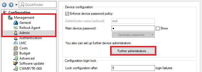 Image depicting a software configuration interface with options for enforcing device password policy, generating administrator name, setting up device administrator, advanced software updates, and login lock configurations.
5.2) Create a further administrator and edit the following parameters:
- Administrator: Enter a descriptive name for the further administrator.
- Password: Enter a password for the administrator.
- Access rights: Select None in the dropdown menu.
- Deactivate all Function rights except Public spot wizard (add user) and Public spot wizard (manage user), so that the further administrator is able to add and manage Public Spot users.
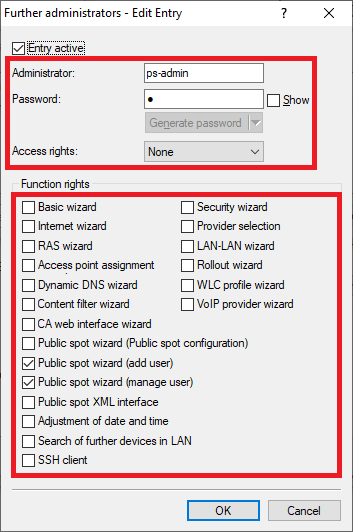 Image of a complex technical user interface displaying various configuration options, including password settings, access rights, wizards for security, internet, and network configurations, Dynamic DNS, content filtering, VoIP services, and public spot management tools.
5.3) The configuration of the further administrator is complete. Write the configuration back into the device.
6) Adding and managing Public Spot users in WEBconfig:
6.1) Invoke the IP address of the gateway router in a web browser and login with the login credentials of the further administrator (see step 5.2)).
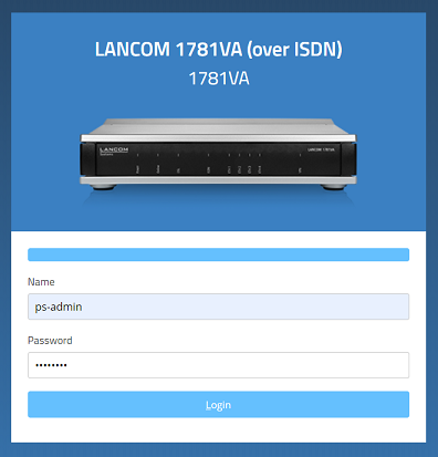 Generischer Alt-Text für Bild
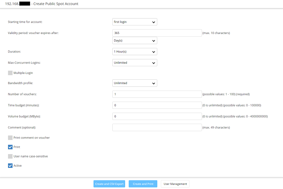
 6.2) It is possible to carry out the following actions in the menu Create Public Spot Account:
- Create one or several Public Spot users by clicking on the button Create and Print.
- Create one or several Public Spot users by clicking on the button Create and CSV-Expor. Additionally the user data will be exported into a CSV file so that it can be processed further.
- By clicking on the button User Management you can invoke the menu Manage Public Spot Account.
 Screenshot of a user interface displaying options to create a public spot account alongside an active print command.
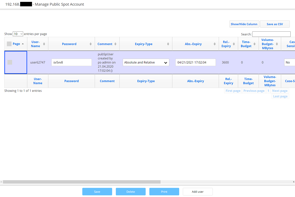
6.3) It is possible to carry out the following actions in the menu Manage Public Spot Account:
- The button Show/Hide column allows to mask individual columns. In the default setting all columns are displayed.
- By clicking Save as CSV a CSV file can be saved which contains all Public Spot users in the database.
- It is possible to change individual parameters (e.g. the Password or Expiry-Type) and save them.
- By clicking the button Delete you can delete individual users.
- By clicking on the button Print you can print vouchers for Public Spot users after creating them.
- By clicking on the button Add user you can invoke the menu Create Public Spot Account.
 Screenshot of a user interface for managing public spot accounts, displaying options to show IO Jenries per page settings.
