Description:
This article describes how to set up VLAN on a switch with LCOS SX 5.xx.
For the VLAN setup, please also refer to the Knowledge Base article VLAN tagging modes explained.
Requirements:
- One of the following LANCOM switch models:
- XS-51xx / XS-6128QF
- GS-45xx / XS-45xx
- CS-8132F
- YS-7154CF
- LCOS SX as of version 5.00 for XS-51xx / XS-6128QF (download latest version)
- LCOS SX as of version 5.20 for GS-45xx / XS-45xx (download latest version)
- LCOS SX as of version 5.30 for CS-8132F and YS-7154CF (download latest version)
- Any web browser for access to the web interface
Scenario:
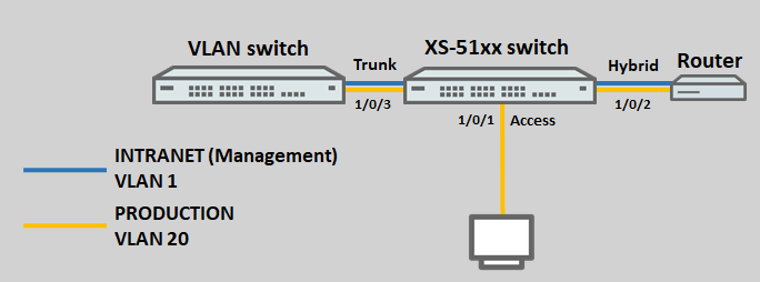
The default VLAN 1 should be operated along with the VLAN 20.
To illustrate the configuration of the tagging modes, the ports 1/0/1 to 1/0/3 are assigned the following tagging modes:
- 1/0/1: Access with the port VLAN ID 20
- 1/0/2: Hybrid with the port VLAN ID 1
- 1/0/3: Trunk
Procedure:
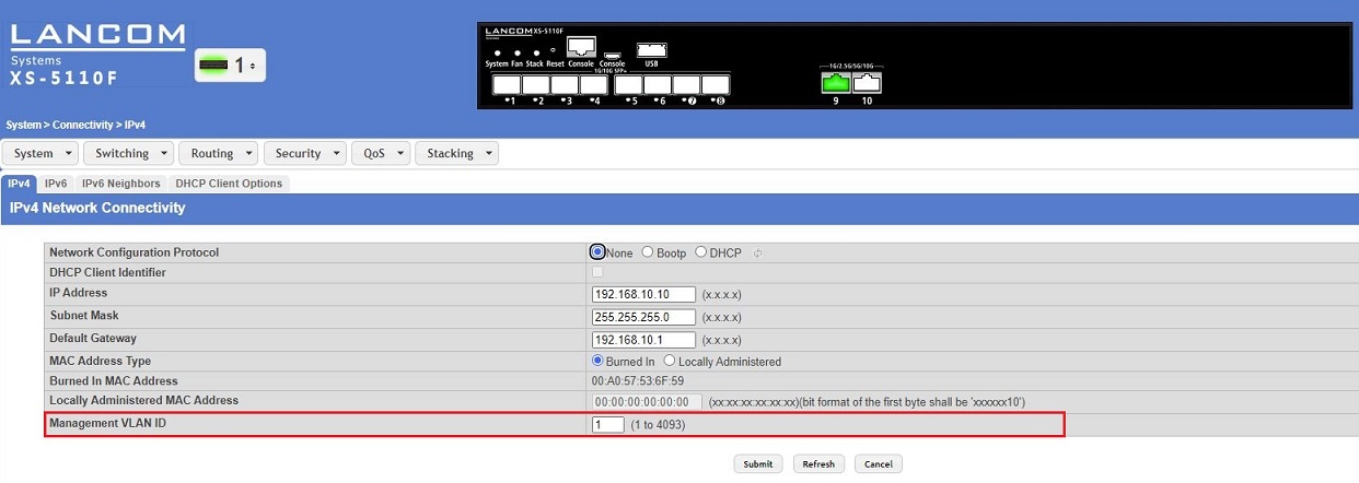
Changing the management VLAN:
A switch is administered via the management VLAN. The management VLAN is set in the menu System → Connectivity → IPv4.
A switch with LCOS SX 5.xx can be administered from the management VLAN and also from any other network if the switch has an IP address in this network.
It is not possible to set up routing for the management VLAN.
Setting up the VLAN function:
The tagging modes for the VLAN are configured in two parts in the menus Switching → VLAN → Port Configuration and Switching → VLAN → Port Summary. You have to complete the configuration in both menus for the VLAN to work correctly.
VLAN tagging modes can also be set in the menu Switching → VLAN → Switchport Summary using the option Switchport Mode. Be sure to leave this at the default setting General, otherwise conflicts will occur and communication will fail!
1) Adding a VLAN ID:
1.1) Connect to the switch via the web interface and navigate to the menu Switching → VLAN → Overview and click Add.
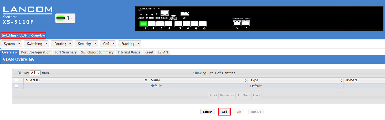
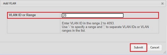
1.2) Enter the desired VLAN ID (in this example the VLAN 20) and click on Submit.
2) Configuring the tagging modes:
2.1) General description of the menus and parameters:
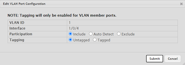
2.1.1) Description of the menu Switching → VLAN → Port Configuration:
This menu configures the tagging behavior for the VLAN and for a specific interface. For this reason each interface has to be configured separately for each VLAN.
Participation:
- Include: The VLAN is allowed on this interface.
- Auto-Detect: The switch detects the setting automatically. This setting should not be used during configuration.
- Exclude: The VLAN is denied on this interface.
Tagging:
- Untagged: The packet that is outbound from the switch is not tagged (Access and Hybrid for the port VLAN ID).
- Tagged: The outbound packet is tagged (Trunk and hybrid for the tagged VLANs).
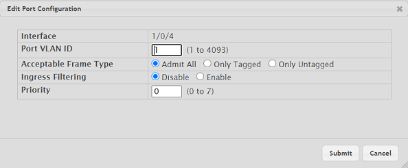
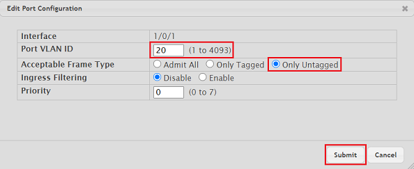
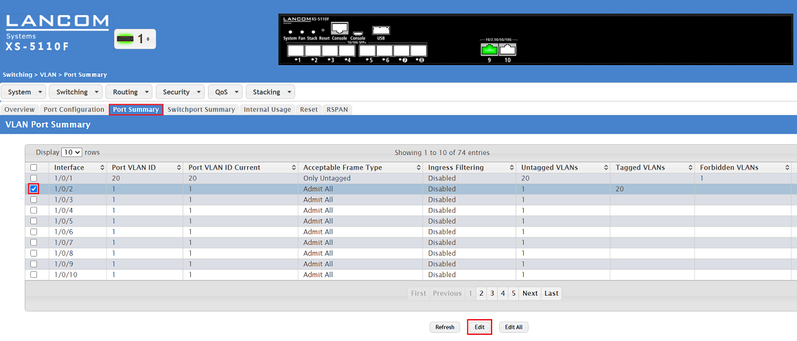
2.1.2) Description of the menu Switching → VLAN → Port Summary:
This menu configures the tagging behavior for a specific interface. Also, the port VLAN ID is saved here (if necessary).
- Port VLAN ID: Enter the VLAN ID that is appended to any incoming packet without a VLAN tag.
- Acceptable Frame Type:
- Admit All: Tagged and untagged packets are allowed on this interface.
- Only Tagged: Tagged packets only are allowed on this interface.
- Only Untagged: Untagged packets only are allowed on this interface.
2.2) Access tagging mode:
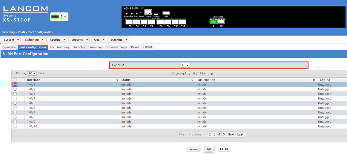
2.2.1) Change to the Port Configuration tab and make sure that VLAN ID 1 is selected. Then select the interface 1/0/1 and click Edit.
You can edit all of the interfaces at the same time by clicking the button Edit All. It is also possible to check multiple interfaces and click on Edit to edit all of them at the same time. The same settings are saved for all of them.
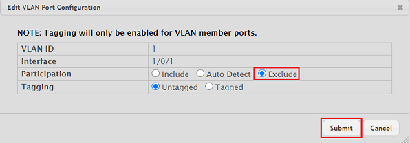
2.2.2) Set the Participation parameter to Exclude so that VLAN 1 cannot communicate through interface 1/0/1. Then click on Submit.
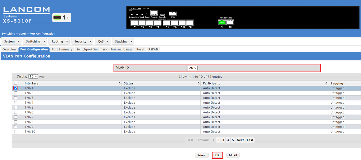
2.2.3) Select the VLAN ID 20 created in step 1. Then select the interface 1/0/1 and click Edit.
You can edit all of the interfaces at the same time by clicking the button Edit All. It is also possible to check multiple interfaces and click on Edit to edit all of them at the same time. The same settings are saved for all of them.
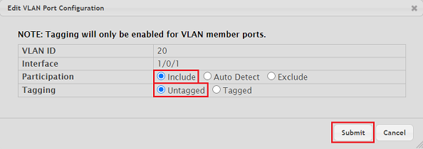
2.2.4) Modify the following parameters and click Submit:
- Participation: Select the option Include so that VLAN 20 may communicate via the interface.
- Tagging: Select the option Untagged.
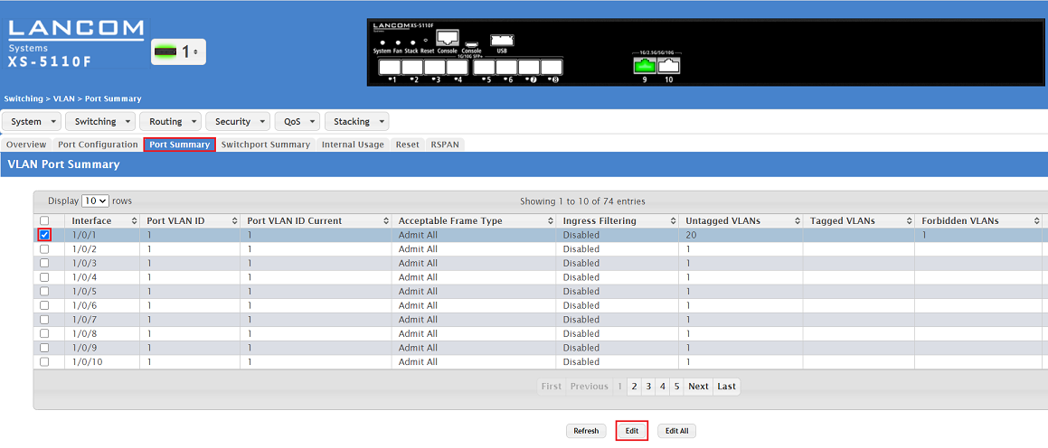
2.2.5) Change to the tab Port Summary, mark the interface 1/0/1 and click on Edit.
You can edit all of the interfaces at the same time by clicking the button Edit All. It is also possible to check multiple interfaces and click on Edit to edit all of them at the same time. The same settings are saved for all of them.
2.2.6) Modify the following parameters and click Submit:
- Port VLAN ID: Enter the VLAN ID that is appended to an incoming packet that has no VLAN tag (in this example the PVID 20).
- Acceptable Frame Type : Select the option Only Untagged .
2.3) Hybrid tagging mode:
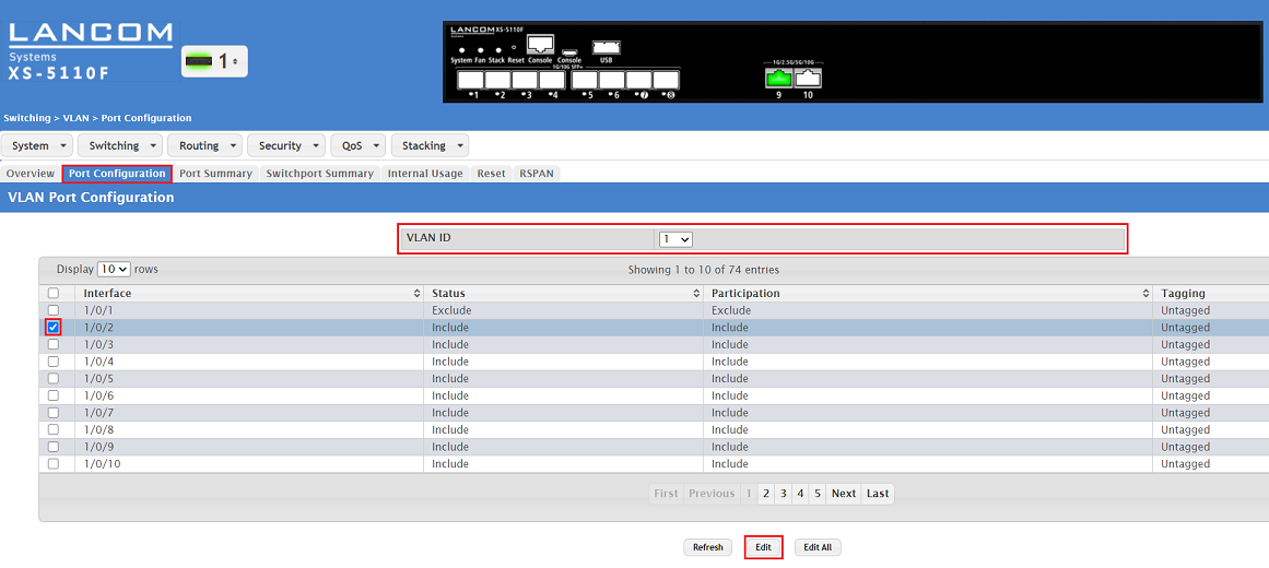
2.3.1) Change to the Port Configuration tab and make sure that VLAN ID 1 is selected. Then select the interface 1/0/2 and click Edit.
You can edit all of the interfaces at the same time by clicking the button Edit All. It is also possible to check multiple interfaces and click on Edit to edit all of them at the same time. The same settings are saved for all of them.
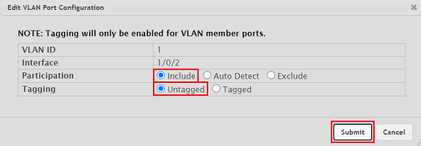
2.3.2) Modify the following parameters and click Submit.
- Participation: Select the option Include so that VLAN 1 may communicate via the interface.
- Tagging: Select the option Untagged.
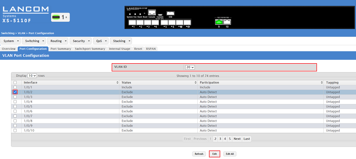
2.3.3) Select the VLAN ID 20 created in step 1. Then select the interface 1/0/2 and click Edit.
You can edit all of the interfaces at the same time by clicking the button Edit All. It is also possible to check multiple interfaces and click on Edit to edit all of them at the same time. The same settings are saved for all of them.
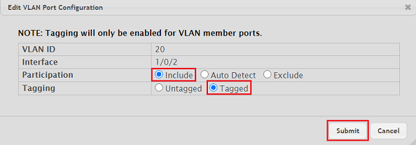
2.3.4) Modify the following parameters and click Submit:
- Participation: Select the option Include so that VLAN 20 may communicate via the interface.
- Tagging: Select the option Tagged.
2.3.5) Change to the tab Port Summary, mark the interface 1/0/2 and click on Edit.
You can edit all of the interfaces at the same time by clicking the button Edit All. It is also possible to check multiple interfaces and click on Edit to edit all of them at the same time. The same settings are saved for all of them.
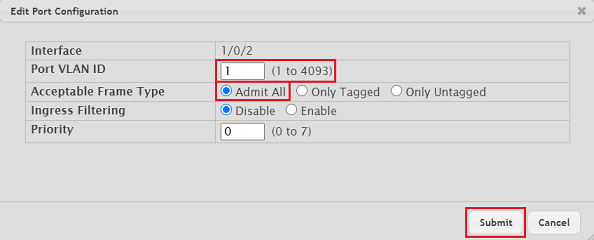
2.3.6) Modify the following parameters and click Submit:
- Port VLAN ID: Enter the VLAN ID that is appended to an incoming packet that has no VLAN tag (in this example the PVID 1).
- Acceptable Frame Type: Select the option Admit All so untagged and tagged packets can be transmitted.
2.4) Trunk tagging mode:
2.4.1) Change to the Port Configuration tab and make sure that VLAN ID 1 is selected. Then select the interface 1/0/3 and click Edit.

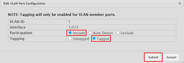
2.4.2) Modify the following parameters and click Submit.
- Participation: Select the option Include so that VLAN 1 may communicate via the interface.
- Tagging: Select the option Tagged.
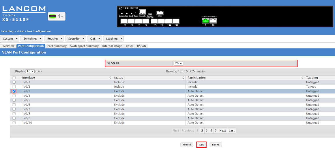
2.4.3) Select the VLAN ID 20 created in step 1. Then select the interface 1/0/3 and click Edit.
You can edit all of the interfaces at the same time by clicking the button Edit All. It is also possible to check multiple interfaces and click on Edit to edit all of them at the same time. The same settings are saved for all of them.
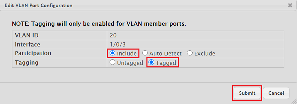
2.4.4) Modify the following parameters and click Submit:
- Participation: Select the option Include so that VLAN 20 may communicate via the interface.
- Tagging: Select the option Tagged.
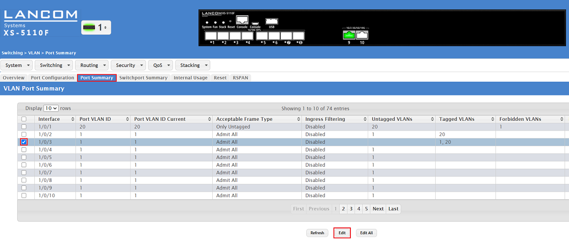
2.4.5) Change to the tab Port Summary, mark the interface 1/0/3 and click on Edit.
You can edit all of the interfaces at the same time by clicking the button Edit All. It is also possible to check multiple interfaces and click on Edit to edit all of them at the same time. The same settings are saved for all of them.
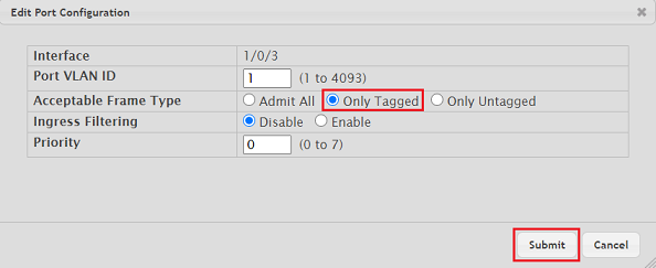
2.4.6) For the Acceptable Frame Type select the option Only Tagged and click Submit.
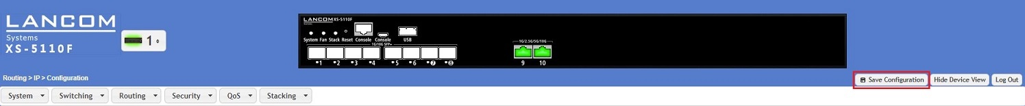
Save the switch configuration as the boot configuration:
With the configuration complete, click on Save Configuration in the top right-hand corner to save the configuration as the boot configuration.
The start configuration is retained even if the device is restarted or there is a power failure.