
Description:
This document describes how to set up a scenario where a single network client on the local network sends all of its data traffic (including Internet data) via a VPN site-to-site connection set up on the LANCOM R&S®Unified Firewall.
Requirements:
- LANCOM R&S®Unified Firewall with LCOS FX as of version 10.5 RU3
- Functional Internet connection
- Web browser for configuring the Unified Firewall.
The following browsers are supported:- Google Chrome
- Chromium
- Mozilla Firefox
- One or more operational VPN site-to-site connections set up on the LANCOM R&S®Unified Firewall (e.g. between two Unified Firewalls)
Scenario:
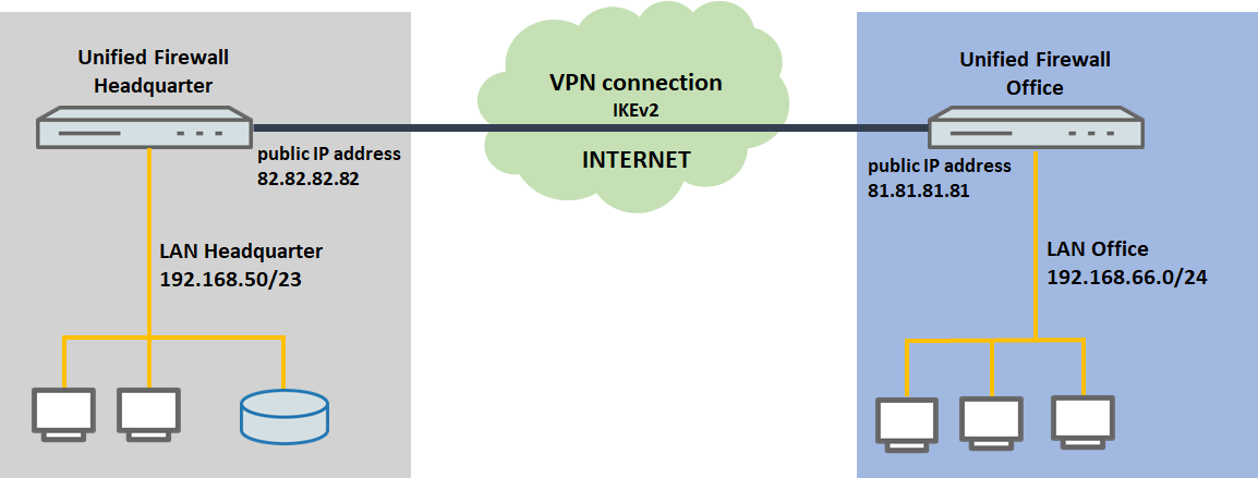
- Between two locations each operating a LANCOM R&S®Unified Firewall, there is an IKEv2 VPN connection, that connects the local network at the branch office (192.168.66.0/24) with the local network at the headquarters (192.168.50.0/23).
- At the branch office, a single network client with the IP address 192.168.66.4 should send all of its data traffic, including Internet data, via the VPN connection to the headquarters.
Procedure:
1) Configuration steps on the Unified Firewall at the branch office:
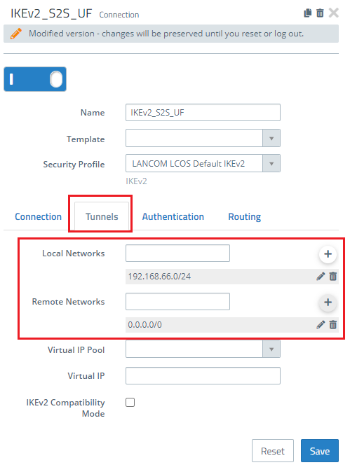
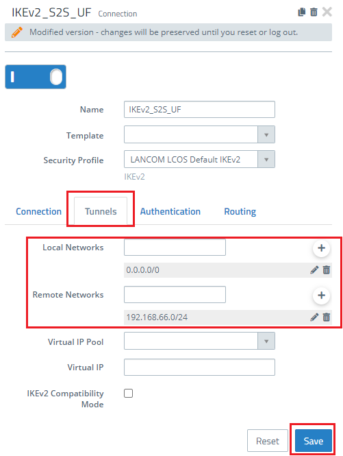
1.1) On the Unified Firewall at the branch office, open the configuration of the VPN connection in the menu VPN → IPsec → Connections and go to the Tunnels tab.
1.2) Modify the entry to create an “Any-to-Any” SA. To do this, fill out the Remote Networks field with the IP address 0.0.0.0/0. In the field Local Networks, enter the local network at the branch office (in this case 192.169.66.0/24).
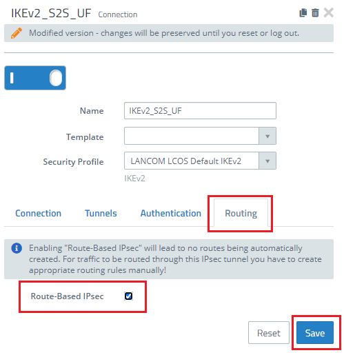
1.3) Switch to the Routing tab and enable the option Routing-based IPsec.
1.4) Save your modifications and go to the menu Network → Routing → Routing Tables. Open Table 254 for editing.
1.5) Create a new entry by clicking the “+” button.
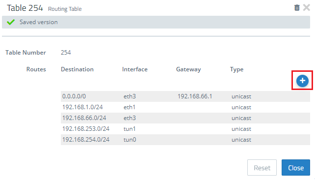
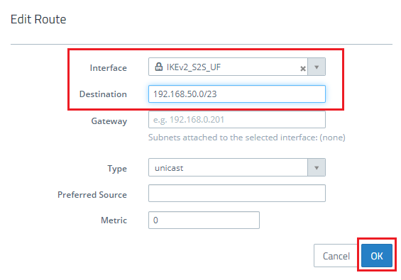
1.6) Set the interface as the VPN site-to-site connection modified in steps 2 and 3.
- Set the destination as the IP address range of the local network at the remote location (i.e. the headquarters).
1.7) Save the entry with OK and close routing table 254.
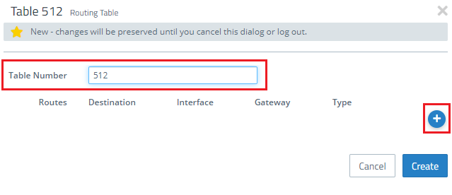
1.8) Create a new routing table using the “+” button.
1.9) Set the table number to 512. Then click the “+” button to create a new entry.
1.10) Set the interface as the VPN site-to-site connection to the headquarters modified in steps 2 and 3.
- Set the destination to the address 0.0.0.0/0.
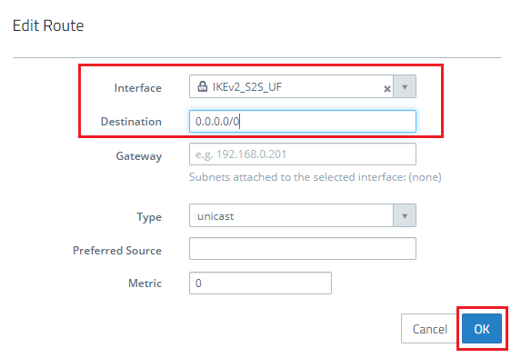
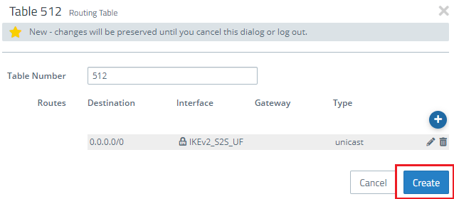
1.11) Save the entry with OK and click Create to close routing table 512.
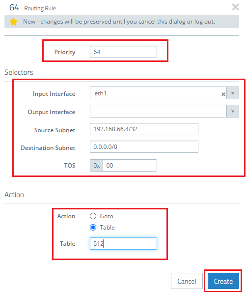
1.12) Go to the menu Network → Routing → Routing Rules and create one new routing rule using the “+” button.
- Set a Priority with a value greater than 64.
- In the field Source Subnet you enter the local IP address of the client that should send all of its data traffic over the VPN connection. In this example, this is the client with the IP address 192.168.66.4. In CIDR notation you have to enter 192.168.66.4/32.
- Set the Destination Subnet to the address 0.0.0.0/0.
- Set the Action as the routing table created as of step 9.
1.13) Save the routing rule with Create.
1.14) This concludes the configuration steps on the Unified Firewall.
2) Configuration steps at the remote site:
2.1) Unified Firewall at the headquarters:
If the remote site operates a LANCOM R&S®Unified Firewall, you need to make the following adjustments to the configuration of the VPN connection:
2.1.1) On the Unified Firewall at the branch office, open the configuration of the VPN connection in the menu VPN → IPsec → Connections and go to the Tunnels tab.
2.2) LANCOM router at the headquarters:
If the remote site operates a LANCOM router, you need to make the following adjustments to the configuration of the VPN connection:
2.2.1) Use LANconfig to open the configuration for the LANCOM router and navigate to the menu item VPN → IKEv2/IPsec → Connection list.
2.2.2) Open the entry for the VPN connection to the branch office.
- Set Rule creation to Manual.
- Set the IPv4 rule to the ready-made rule RAS-WITH-NETWORK-SELECTION.
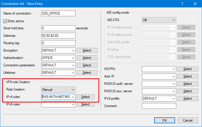
2.2.3) Save your modifications with OK and write the configuration back to the LANCOM router.