Description:
Communication between different networks of a router can either be restricted via firewall rules or via interface tags. For simple scenarios, interface tags are a good choice due to the low configuration effort required.
For more complex scenarios, where communication to another network is allowed or forbidden only for individual members, using the interface tags is not recommended, as in this case an additional firewall rule would be needed to remove the interface tag and set the correct tag.
This article describes, how communication between different local networks on a router with WLAN can be restricted via interface tags.
Please note the following Knowledge Base articles regarding the network separation via ARF for additional device types (routers without permanently active Private Mode and routers with WLAN):
Requirements:
- LANCOM routers with WLAN
- LCOS as of version 9.24 (download latest version)
- LANtools as of version 9.24 (download latest version)
- Configured WLAN for this scenario on the logical interfaces WLAN-1 (employee network) and WLAN-1-2 (guest network)
Scenario:
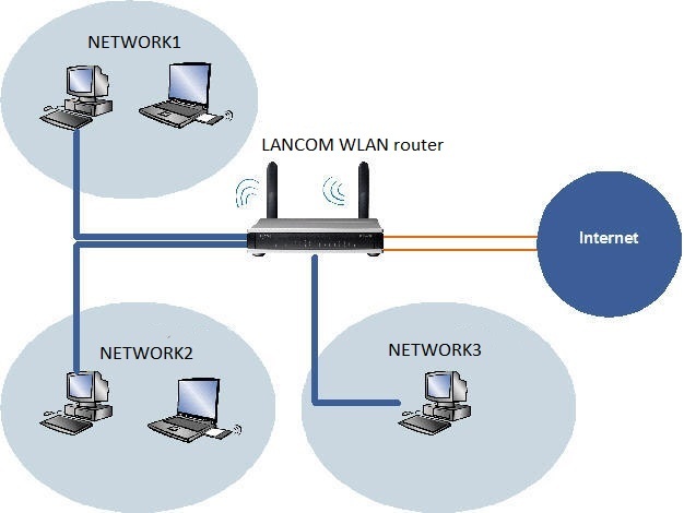
The aim is to restrict access between the networks NETWORK1, NETWORK2 and NETWORK3 on the LAN and WLAN side of the router.
- NETWORK1 with the Interfaces LAN-1 (ETH 1) and WLAN-1 has the Network ID: 172.16.1.0 and as an employee network should provide access to all other local networks and to the Internet.
- NETWORK2 with the Interfaces LAN-2 (ETH 2) and WLAN-1-2 has the Network ID: 172.16.2.0 and as a guest network should provide access to the Internet only.
- NETWORK3 with the Interface LAN-3 (ETH 3 and ETH 4) has the Network ID: 172.16.3.0 and as a server network should not have active access to any other network; however, NETWORK1 should have access to these servers.
Procedure:
- Interface tags can be allocated to the IP networks. This gives you control over the communication between the networks. Routing tags can be allocated in the routing table.
- When combined with the interface tags, these make it possible to control which route may be used by which local network.
1) Assigning the interfaces to the networks:
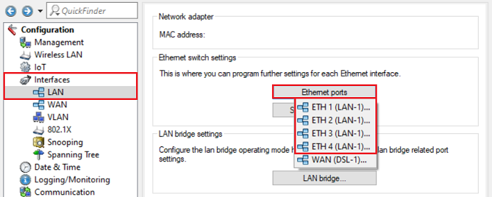
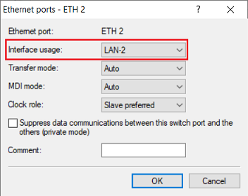
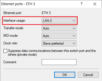
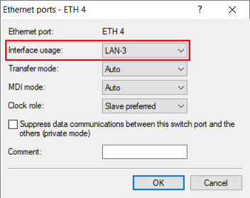
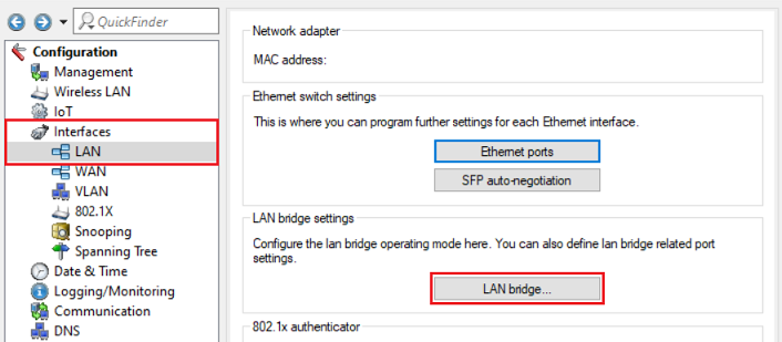
1.1) Open the configuration of the router in LANconfig and edit the Ethernet interfaces ETH 1 to ETH 4 in the menu Interfaces → LAN → Ethernet ports.
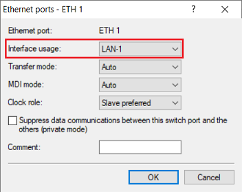
1.2) Make sure, that the logical interface LAN-1 is assigned the physical Ethernet interface 1 (ETH 1).
1.3) Assign the logical interface LAN-2 to the physical Ethernet interface 2 (ETH 2).
1.4) Assign the logical interface LAN-3 to the physical Ethernet interfaces 3 and 4 (ETH 3 and ETH 4).
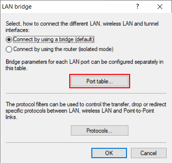
1.5) Go to the menu Interfaces → LAN → LAN bridge to combine interfaces in a bridge.
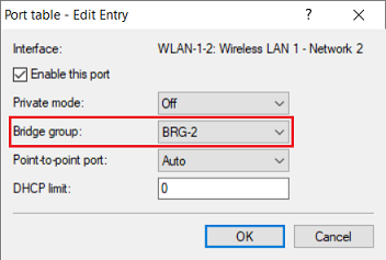
1.6) Switch to the menu Port table.
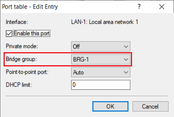
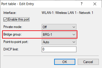
1.7) Make sure, that the bridge group BRG-1 is assigned to the logical interfaces LAN-1 and WLAN-1.
When using a WLAN router with two WLAN modules the interface WLAN-2 also has to be included in the bridge group BRG-1.
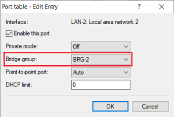
1.8) Assign the bridge group BRG-2 to the logical interfaces LAN-2 and WLAN-1-2.
When using a WLAN router with two WLAN modules the interface WLAN-2-2 also has to be included in the bridge group BRG-2.
A bridge group for the physical interfaces ETH 3 and ETH 4 is not necessary, as these are already combined in the logical interface LAN-3.
2.) Assigning the logical interfaces and interface tags to the IP networks:
- IP networks with the interface tag 0 can access all other networks.
- IP networks with an interface tag in the range 1-65535 can only access IP networks that use the same interface tag.
You can check the assignment of the IP addresses to the interfaces via the CLI command show ipv4-addresses.
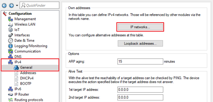
2.1) Go to the menu IPv4 → General → IP networks.
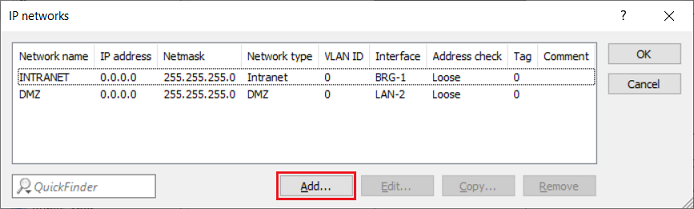
2.2) Click Add and subsequently create three new networks.
The entries INTRANET and DMZ should not be removed. As these are also referenced in other menus (e.g. in the DHCP networks) without additional configuration changes this would result in the configuration no longer being able to be written via LANconfig!
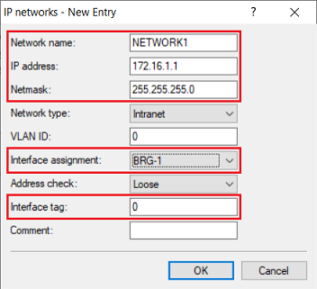
2.3) Modify the following parameters for the employee network:
- Network name: Enter a descriptive name for the network (in this example NETWORK1).
- IP address: Enter an IP address for this network (in this example 172.16.1.1).
- Netmask: Enter a subnetmask for this network (in this example 255.255.255.0).
- Interfaces assignment: Make sure, that the interface BRG-1 is selected.
- Interface tag: Make sure, that the tag 0 is stored. This means, that members from this network can access all other local networks.
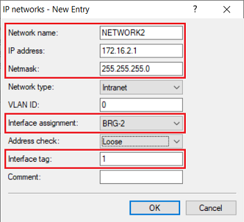
2.4) Modify the following parameters for the guest network:
- Network name: Enter a descriptive name for the network (in this example NETWORK2).
- IP address: Enter an IP address for this network (in this example 172.16.2.1).
- Netmask: Enter a subnetmask for this network (in this example 255.255.255.0).
- Interface assignment: Select the interface BRG-2 from the dropdown menu.
- Interface tag: Enter the tag 1. This means, that members from this network cannot access any other local network.
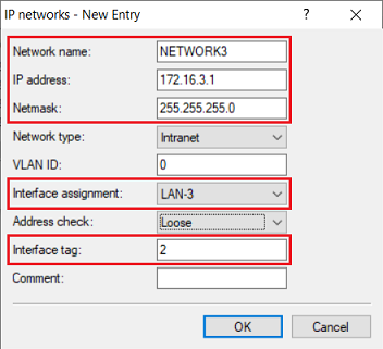
2.5) Modify the following parameters for the server network:
- Network name: Enter a descriptive name for the network (in this example NETWORK3).
- IP address: Enter an IP address for this network (in this example 172.16.3.1).
- Netmask: Enter a subnetmask for this network (in this example 255.255.255.0).
- Interface assignment: Select the interface LAN-3 from the dropdown menu.
- Interface tag: Enter the tag 2. This means, that members from this network cannot access any other local network.
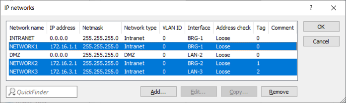
2.6) The list of the IP networks should now appear as follows.
3) Creating the routing entry:
As of LCOS 10.40 there is an own table in the FIB (Forwarding Information Base) for each routing tag.
- Routing entries with an Internet remote site and the routing tag 0 are copied to all tables in the FIB. This means, that communication from all networks via an Internet connection with routing tag 0 is possible.
- Routing entries with an Internet remote site and a routing tag unequal 0 are only copied to the table in the FIB with the corresponding routing tag. This means, that only the network with the corresponding tag can communicate via this routing entry.
Additional information regardíng the routing behavior can be found in the LCOS reference manual:
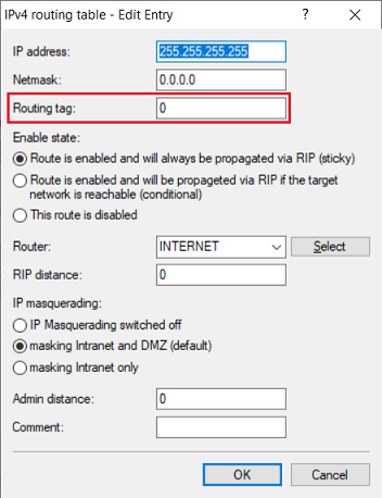
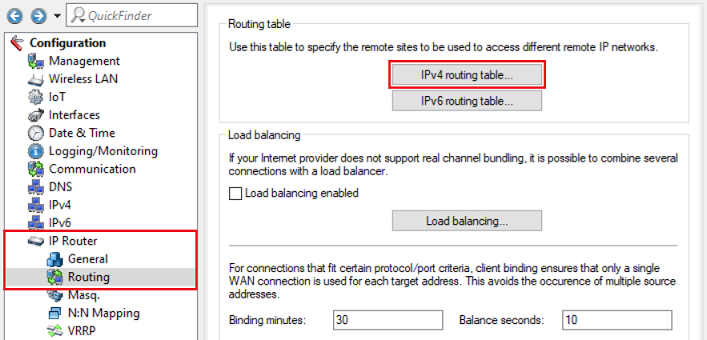
3.1) Go to the menu IP Router → Routing → IPv4 routing table.
3.2) Adjust the routing tag of the default route to your needs. In this example the tag was left at 0, so that all networks can communicate with the Internet via this routing entry.
You can also copy the default route and enter a routing tag unequal to 0. In this case only a network with the same interface tag can communicate via this routing entry.