Description:
This article describes how VLAN is configured on a GS-23xx series switch.
Please note how the different VLAN tagging modes work .
Requirement:
- LANCOM GS-23xx series switch
- LCOS SX as of version 2.83 (download latest version)
- LCOS as of version 8.50 (download latest version)
- LANtools as of version 8.50 (download latest version)
- A LANCOM router that can address at least 3 networks using ARF.
Scenario:
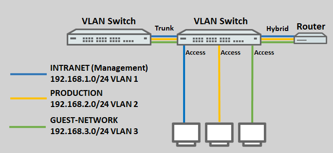
- Three networks are created on the LANCOM router with the VLAN IDs 1, 2 and 3. The management network here is the INTRANET with the VLAN ID 1.
- The logical interface LAN-1 on the router is assigned the tagging mode Hybrid.
- A further VLAN-capable switch is used, which also supports the VLANs 1 – 3. The tagging mode used on this switch is Trunk.
- The ports on the switch are assigned as follows:
- Port 1 is connected to the router.
- Port 2 is connected to the second VLAN-enabled switch.
- Port 3 is connected to an end device that should access the network INTRANET.
- Port 4 is connected to an end device that should access the network PRODUCTION.
- Port 5 is connected to an end device that should access the GUEST NETWORK.
Procedure:
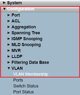
1) Open the webinterface of the switch and go to the menu Configuration → VLAN → VLAN Membership.
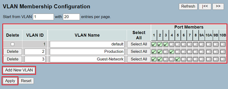
2) Create two additional VLANs for the networks PRODUCTION and GUEST-NETWORK via the button Add New VLAN (VLAN IDs 2 and 3).
3) Change the membership between VLANs and ports as follows:
- VLAN 1: The VLAN 1 is used on the ports 1 - 3. In the default configuration the VLAN 1 is active on all ports. Therefore remove the rest of the ports from the VLAN 1 by clicking on the respective port twice.
- VLAN 2: The VLAN 2 is used on the ports 1,2 and 4. Therefore add these ports to the VLAN by clicking on the respective port once.
- VLAN 3: The VLAN 3 is used on the ports 1,2 and 5. Therefore add these ports to the VLAN by clicking on the respective port once.
4.) Click Apply to accept the configuration changes.
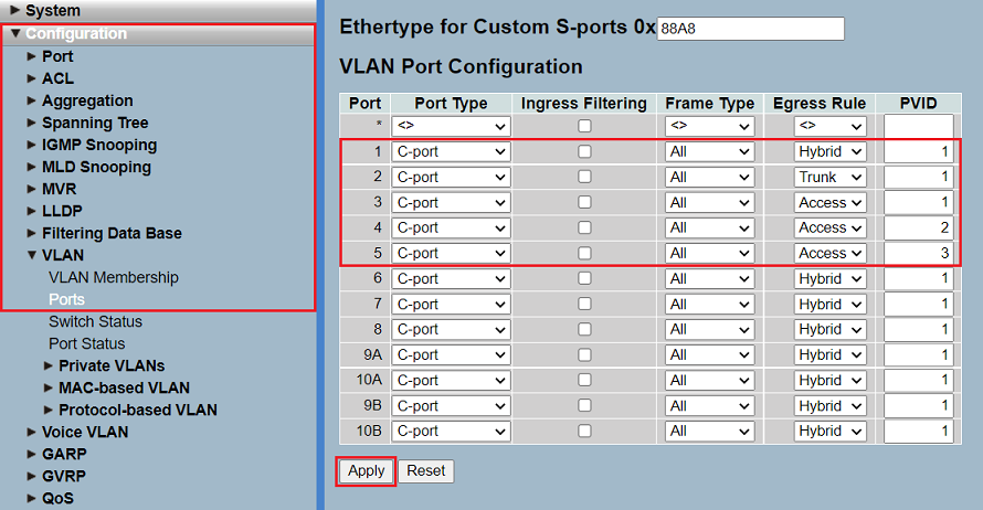
5) Go to the menu Configuration → VLAN → Ports, modify the tagging modes for the individual ports and click Apply.
- Port 1:
- Egress Rule: Select the tagging mode Hybrid, as the router is also set to Hybrid (see Scenario).
- PVID: Enter the VLAN ID 1 because the network INTRANET (VLAN ID 1) acts as a management network.
- Port 2:
- Egress Rule: Select the tagging mode Trunk, as the other switch is also set to Trunk (see Scenario).
- PVID: The VLAN ID can be left at the value 1. When using the Trunk tagging mode, the Port VLAN ID not used.
- Port 3:
- Egress Rule: Select the tagging mode Access, because an end device that does not support VLAN is to be connected.
- PVID: Enter the VLAN ID 1 because access to the INTRANET network requires the VLAN ID 1.
- Port 4:
- Egress Rule: Select the tagging mode Access, because an end device that does not support VLAN is to be connected.
- PVID: Enter the VLAN ID 2 because access to the PRODUCTION network requires the VLAN ID 2.
- Port 5:
- Egress Rule: Select the tagging mode Access, because an end device that does not support VLAN is to be connected.
- PVID: Enter the VLAN ID 3 because access to the GUEST NETWORK requires the VLAN ID 3.
Make absolutely sure, that the Port Type is set to C-port for all ports. Only with this option the regular tagging behavior is used. In the default configuration the option C-port is assigned to all ports.
6).Go to the menu Maintenance → Save/Restore → Save Start and click Save to save the configuration as the start configuration.
The start configuration is retained even if the device is restarted or there is a power failure.
Troubleshooting: No communication within a VLAN on a specific switch port
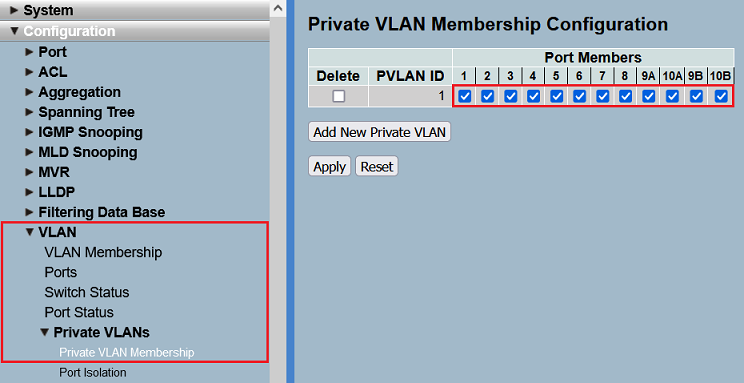
When a Private VLAN has been created, a switch port must be a member of the respective VLAN as well as the corresponding Private VLAN for the communication to be possible.
Therefore go to the menu Configuration → VLAN → Private VLANs → Private VLAN Membership and make sure, that all ports are a member of the respective VLAN.
In the default configuration all switch ports are a member of the Private VLAN 1. Therefore only the VLAN 1 is affected unless additional Private VLANs are added.

