
Description:
This article describes the procedure for replacing a switch with LCOS SX 5.xx (e.g. due to a hardware defect) in the LANCOM Management Cloud (LMC).
Requirements:
- One of the following LANCOM switch models:
- XS-51xx / XS-6128QF
- GS-45xx / XS-45xx
- CS-8132F
- YS-7154CF
- LCOS SX as of version 5.10 for XS-51xx / XS-6128QF (download latest version)
- LCOS SX as of version 5.20 for GS-45xx / XS-45xx (download latest version)
- LCOS SX as of version 5.30 for CS-8132F and YS-7154CF (download latest version)
- Any web browser for access to the web interface
- Access to the LMC including your own project
1) Preparations: Save the switch configuration of the device being replaced
Save the startup configuration using either the web interface, LANconfig or SCP.
2) Procedure for exchanging the device:
2.1) Remove the device being replaced from the LMC project:
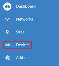
2.1.1) Connect to the LMC and navigate to the menu Devices.
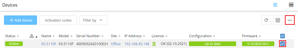
2.1.2) Mark the device to be exchanged and click on the “dots” icon to call up the advanced menu.
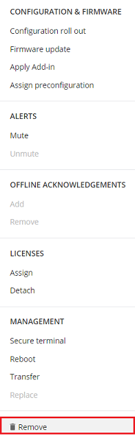
2.1.3) Click Remove.
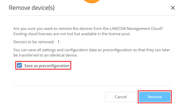
2.1.4) Make sure that the option Save as preconfiguration is selected and click Remove.
2.2) Connect the new device with the LMC:
If your project uses rollout parameters (rollout project, rollout location, rollout role, domain for private LMC), these parameters must be set manually on the replacement device in advance.
The replacement device must still be in the factory state and, apart from the rollout parameters, must not yet be configured!
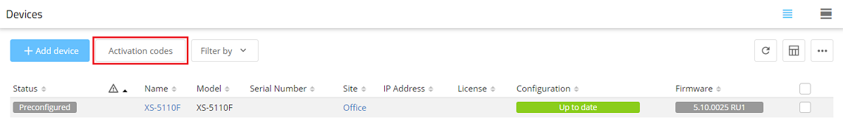
2.2.1) In the project in the LMC, switch to the Devices menu.
2.2.2) Click the Activation codes button.
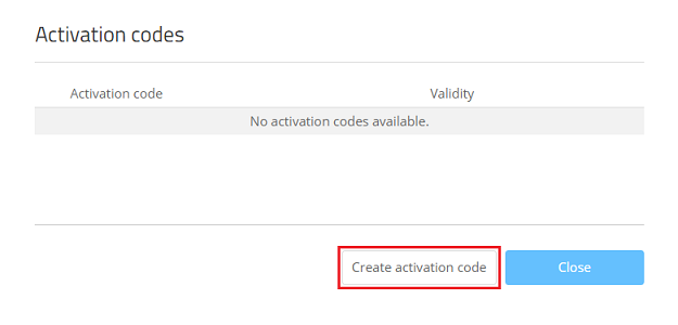
2.2.3) Click on Create activation code.
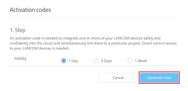
2.2.4) Set its Validity and click on Generate now.
Usually a validity of 1 day is perfectly adequate.
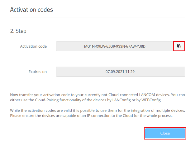
2.2.5) Copy the Activation code and click Close.
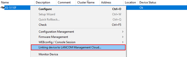
2.2.6) Select the replacement device in LANconfig, right-click on it and, from the context menu, choose the option Linking device to LANCOM Management Cloud.
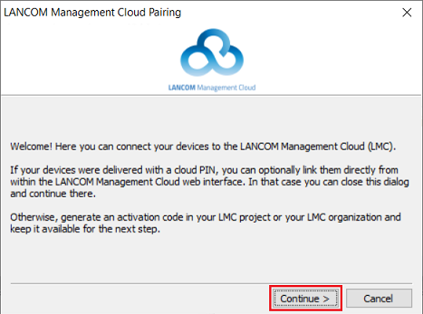
2.2.7) Click Continue.
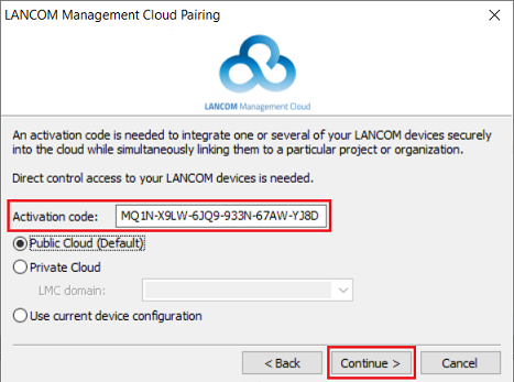
2.2.8) Check that the Activation code was accepted correctly and then click Continue.
If the Activation code was copied to the Clipboard, it is taken over automatically. If not, enter it manually.
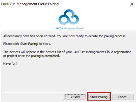
2.2.9) Click Start pairing to launch the process with the LMC.
2.3) Assigning the license and rolling out the preconfiguration to the replacement device:
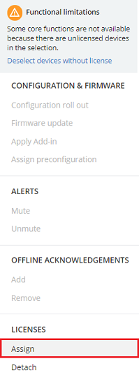
2.3.1) In the Devices menu, mark the replacement device and click on the “dots” icon to call up the advanced menu.
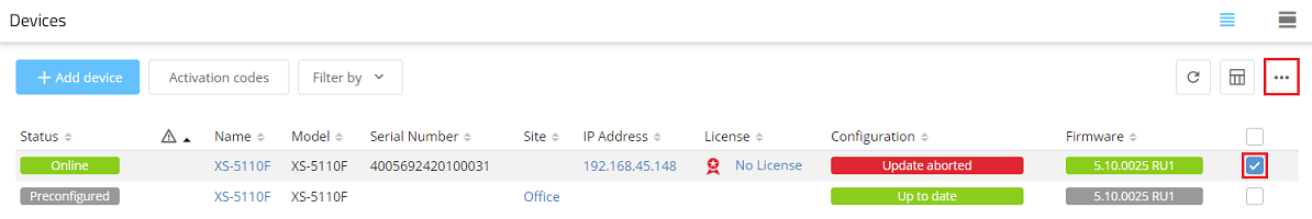
2.3.2) Under Licenses, click on Assign.
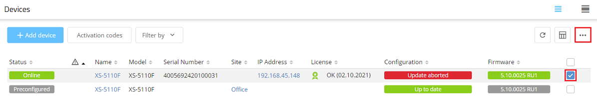
2.3.3) Select an available and suitable license and click on Assign license.

2.3.4) Mark the replacement device and click on the “dots” icon to call up the advanced menu again.
2.3.5) Click on Assign preconfiguration to rollout the preconfiguration created in step 2.1.4 to the device.
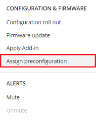
2.3.6) Select the appropriate preconfiguration and click Assign.

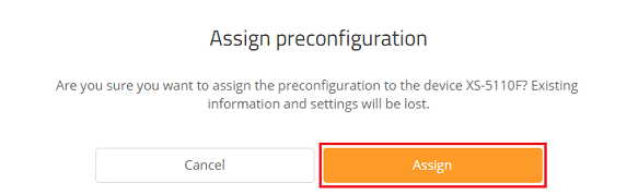
2.3.7) Confirm the prompt by clicking on Assign.
2.4) Upload the switch configuration to the replacement device (only in the case of a manual configuration of certain parameters without the LMC):
If certain parameters on the old device were set manually in the configuration instead of rolling them out via the LMC or LMC add-ins (e.g. LACP or SNMP settings), the configuration backup saved in step 1 can be uploaded to the replacement device.
Skip this step if—as recommended—the entire configuration is carried out via the LMC or LMC add-ins.
2.4.1) Upload the configuration backup saved in step 1 onto the replacement device:
- Uploading the switch configuration via the web interface
- Uploading the switch configuration via LANconfig
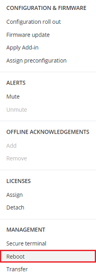
2.4.2) In the Devices menu, mark the replacement device and click on the “dots” icon to call up the advanced menu.
Alternatively, you can restart the system using the web-interface menu System → Utilities → System Reboot or briefly disconnect the device from the power supply.

2.4.3) Click Reboot.
2.5) Exchanging the switch:
2.5.1) Disconnect the device to be replaced from the power supply.
2.5.2) Replace the old switch with the new device and reconnect the network cables.
3) Final steps: Check that the configuration was transferred successfully
Check the Detail configuration of the replacement switch to see whether the configuration was correctly transferred to the new device.
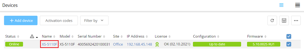
3.1) In the Devices menu, click the Name to access the device settings.
3.2) Change to the Detail configuration tab and click on the “dots” icon to open the advanced menu.
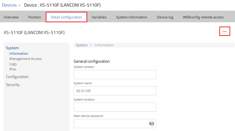
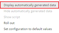
3.3) Click on Display automatically generated data so that the configuration components generated by the LMC are displayed in the detail configuration.
3.4) Now check the configuration.