
Description:
This article describes how routing via an intermediate network is set up between the networks of a LANCOM R&S®Unified Firewall and a LANCOM router.
Requirements:
- LCOS FX as of version 10.7 (download latest version)
- LCOS as of version 9.24 (download latest version)
- LANtools from version 9.24 (download latest version)
- Web browser for configuring the Unified Firewall
The following browsers are supported:- Google Chrome
- Chromium
- Mozilla Firefox
Scenario:
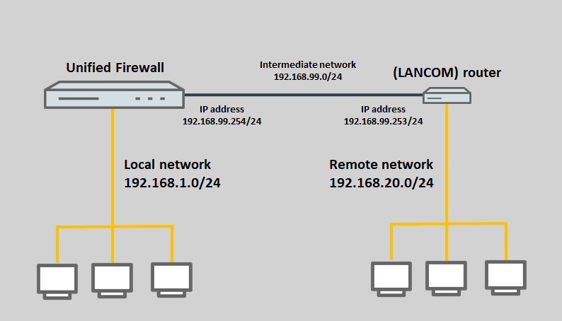
- The Unified Firewall is configured with the network 192.168.1.0/24.
- A router is configured with the network 192.168.20.0/24.
- The Unified Firewall and the router should be configured with the intermediate network 192.168.99.0/24 and routing should be set up between the networks of the unified firewall and the router.
The LANCOM router cannot be located in the local network with the unified firewall, otherwise the router would send the response packets directly to the devices in this network and not to the Unified Firewall. The Unified Firewall would then discard any further packets that belong to the same session.
The same applies in the other direction. The Unified Firewall cannot be in the network of the LANCOM router.
Procedure:
1) Configuration steps on the Unified Firewall:
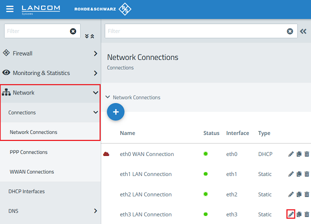
1.1) Connect to the Unified Firewall, go to the menu Network → Connections → Network Connections and click the “pencil” icon to edit the settings for a previously unused interface (in this example eth3).
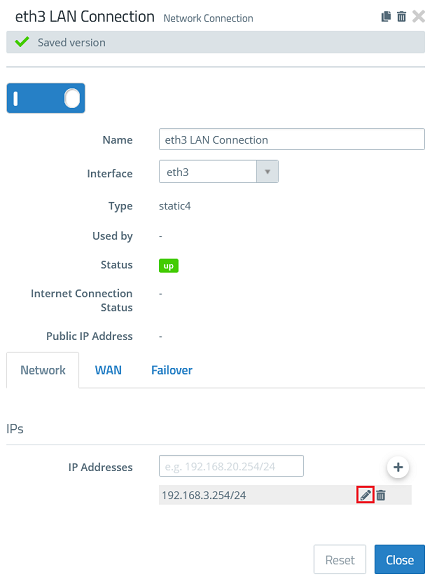
If the currently assigned IP address of the selected interface (default setting for eth3 is 192.168.3.254) should be used for the intermediate network, you can skip the steps 1.1 – 1.3.
1.2) Click the “pencil” icon to adjust the stored IP address.
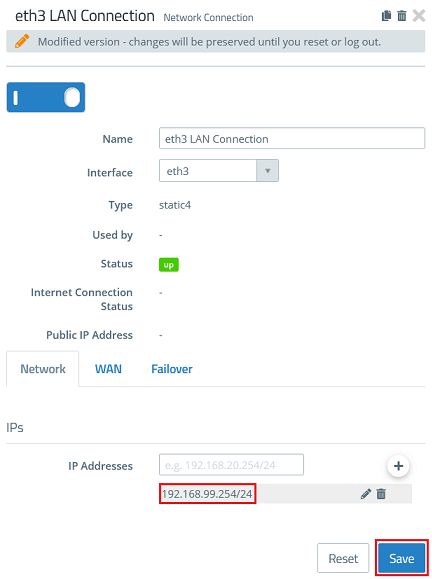
1.3) Enter an IP address from a previously unused network in CIDR notation (Classless Inter Domain Routing), which is to operate as an intermediate network between the Unified Firewall and the separate router (in this example 192.168.99.254). Then click Save.
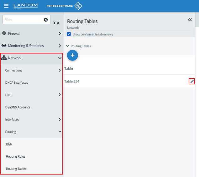
1.4) Change to the menu Network → Routing → Routing Tables and click the “pencil” icon to edit Table 254.
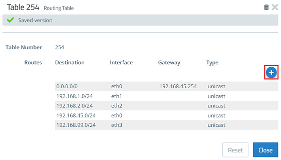
1.5) Click the “+” icon to create a new routing entry.
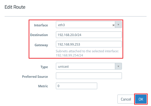
1.6) Modify the following parameters and then click OK:
- Interface: Select the interface chosen in step 1.1, which is in the intermediate network (in this example eth3).
- Destination: Enter the network address of the target network to be reached via the router, in CIDR notation (in this example 192.168.20.0/24).
- Gateway: Enter an available IP address from the intermediate network to be used by the router (in this example 192.168.99.253).
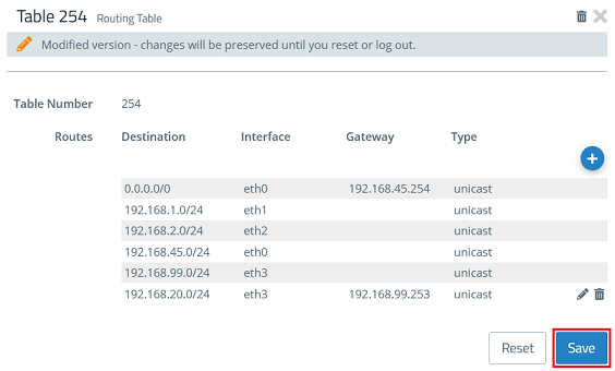
1.7.) Click Save.
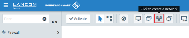
1.8) Click the button to create a network.
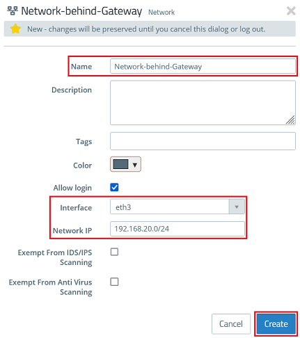
1.9) Modify the following parameters and then click Create:
- Name: Enter a descriptive name (in this example Network-behind-Gateway).
- Interface: From the drop-down menu, select the interface connected to the intermediate network (in this example eth3).
- Network IP: Enter the network address of the target network to be reached via the router, in CIDR notation (in this example 192.168.20.0/24).
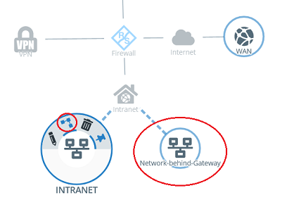
1.10) Click the local network object on the desktop (in this example INTRANET), select the connection tool, and click the network object for the remote network created in step 1.9.
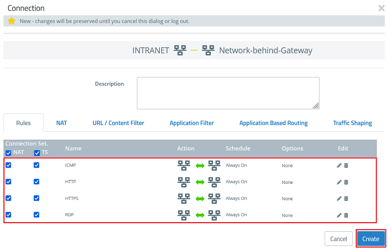
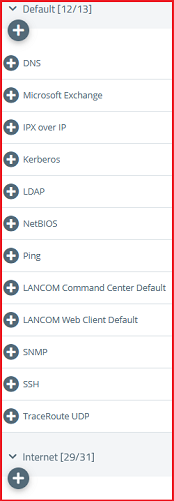
1.11) Select the protocols required for communication and add them using the “+” icon. Then click Create.
The Unified Firewall uses a deny-all strategy. You therefore have to explicitly allow communication.
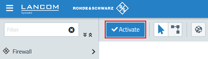
1.12) Finally, implement the changes by clicking Activate.
2) Configuration steps on the LANCOM router:
If you are using a router from another manufacturer, use the manual or approach the manufacturer for information about the appropriate procedure.
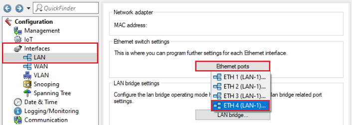
2.1) Using LANconfig, connect to the router, switch to the menu Interfaces → LAN → Ethernet ports and choose a previously unused Ethernet port off (in this example ETH 4).
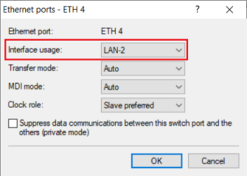
2.2) From the drop-down menu for Interface usage, select a previously unused logical interface (in this example LAN-2).
2.3) Navigate to the menu Interfaces → LAN → LAN bridge.
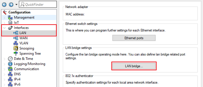
2.4) Go to the Port table menu.
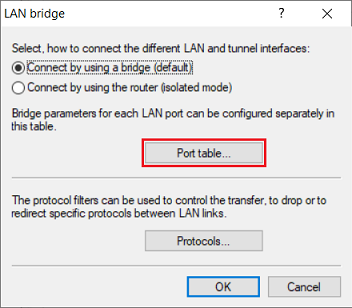
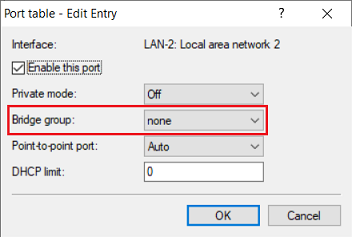
2.5) Make sure that the logical interface assigned in step 2.2 (in this example LAN-2) is not assigned to a bridge group.
2.6) Switch to the menu IPv4 → General → IP networks.
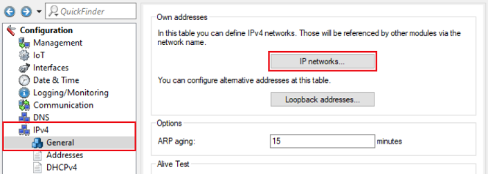
2.7) Click Add to create a new network.
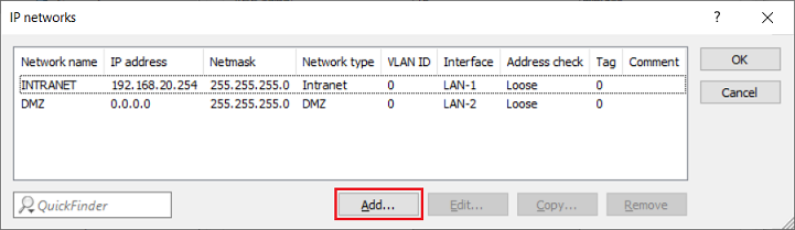
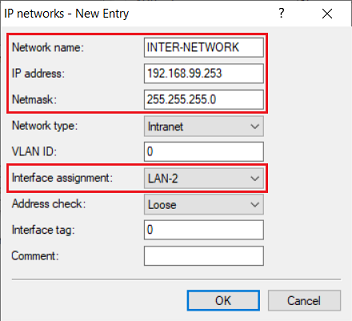
2.8) Change the following parameters:
- Network name: Enter a descriptive name (in this example INTER-NETWORK).
- IP address: Enter the gateway IP address from the intermediate network set in step 1.6 (in this example 192.168.99.253).
- Netmask: Enter the corresponding subnet mask.
- Interface assignment: From the drop-down menu, select the logical interface that was set in step 2.2 (in this example LAN-2).
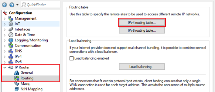
2.9) Navigate to the menu IP Router → Routing → IPv4 routing table.
2.10) Click Add to create a new routing entry.
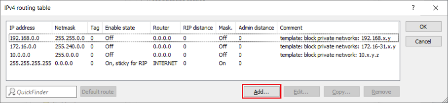
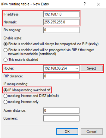
2.11) Change the following parameters:
- IP address: Enter the network address of the network with the Unified Firewall (in this example 192.168.1.0).
- Netmask: Enter the corresponding subnet mask.
- Router: Enter the IP address of the Unified Firewall in the intermediate network assigned in steps 1.2 - 1.3 (in this example 192.168.99.254).
- IP masquerading: Select the option IP masquerading switched off.
2.12) This concludes the configuration steps on the LANCOM router. You can now write the configuration back to the device.
The firewall in LANCOM routers uses an implicit allow-all strategy. Communication is therefore permitted until it is prevented.