
Description:
For some scenarios, it may be sufficient to provide a guest network in the LAN only. This may be the case where access points already exist and an IP address from the guest network should be assigned to them. With just a few changes to the configuration, the guest network can be used both in the LAN and in the Wi-Fi, provided that there is a router with an integrated WLAN module available.
This article describes how to set up a simple guest network in the LAN or LAN/Wi-Fi on a LANCOM router.
Requirements:
- LCOS as of version 8.50 (download latest version)
- LANtools as of version 8.50 (download latest version)
- LANCOM router without Wi-Fi (only scenario 1) respectively with integrated Wi-Fi (scenario 1 and 2)
- Existing and functional internal network
- Existing and functional Internet connection
Scenario:
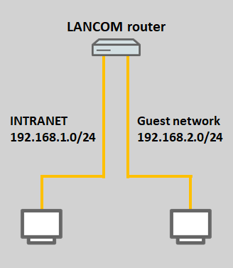
Scenario 1: The guest network is provided on the LAN only
- A guest network should be provided on the LAN along with the existing internal network.
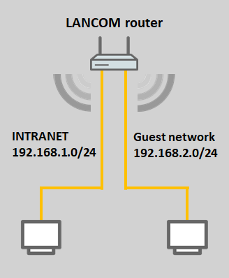
Scenario 2: The guest network is provided both in the LAN and on the Wi-Fi
- A guest network should be provided on the LAN and on the Wi-Fi along with the existing internal network.
This scenario requires a router with an integrated WLAN module.
If additional access points should be used to transmit the Wi-Fi for both networks, you will need to use VLAN. This scenario is described in this Knowledge Base article.
Procedure:
The configuration of both scenarios is basically very similar. In addition to the configuration of the WLAN module, scenario 2 merely requires the modification of a few interface assignments.
1) Configuring a guest network on the LAN:
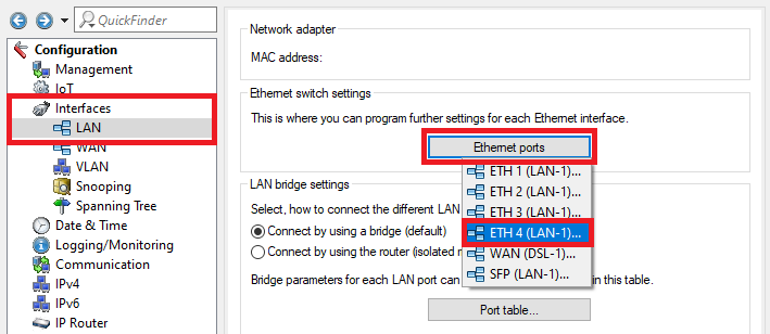
1.1) Open the router configuration in LANconfig, go to the menu Interfaces → LAN → Ethernet ports and choose one of the free Ethernet ports for the guest network.
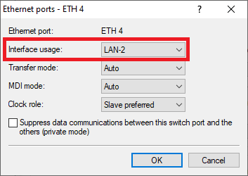
1.2) Assign a previously unused logical LAN interface to the Ethernet port selected in step 1.1 (in this example LAN-2).
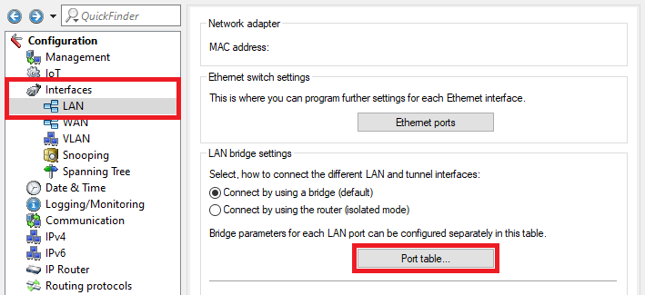
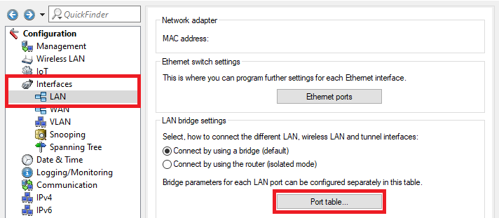
1.3) Go to the Port table menu.
As of LCOS 10.42 the Port table is located in the menu Interfaces → LAN → LAN bridge.
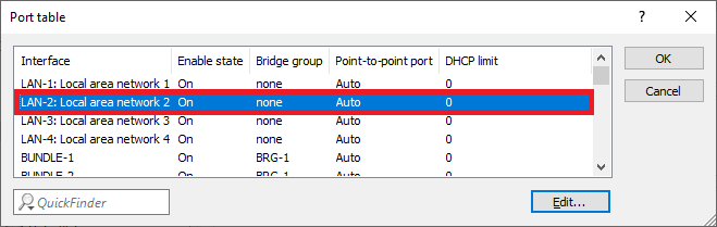
1.4) Make sure that the logical LAN interface assigned in step 1.2 (in this example LAN-2) is not assigned to a bridge group.
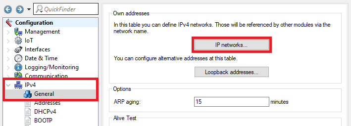
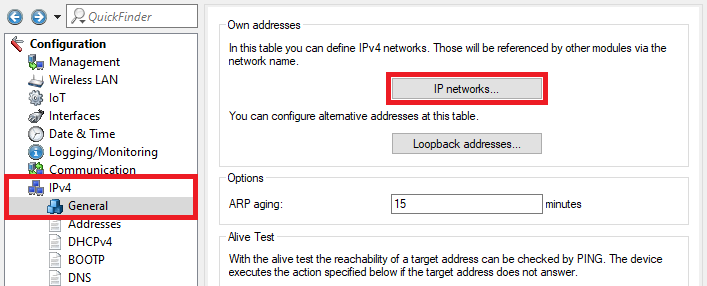
1.5) Switch to the menu IPv4 → General → IP networks.
1.6) Click Add to create the guest network.
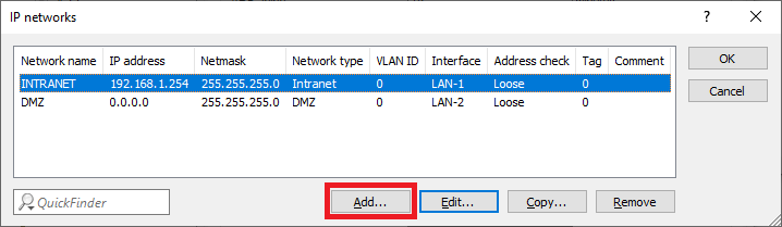
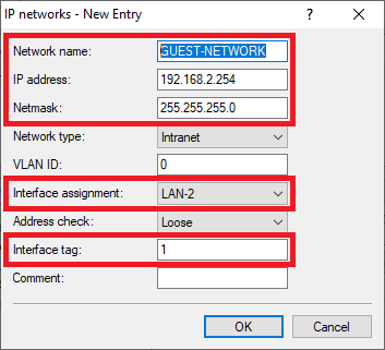
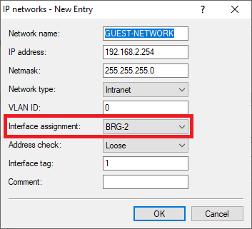
1.7) Enter the following parameters:
- Network name: Enter a descriptive name for the network.
- IP address: Enter an IP address from an as yet unused IP address range.
- Netmask: Enter the subnet mask for the related IP address.
- Interface assignment: From the drop-down menu, select the logical interface that was assigned in step 1.2 (in this example LAN-2).
- Interface tag: Set an interface tag not equal to 0, so that communication between the GUEST network and the INTRANET network is prevented (in this example, tag 1 is used).
Networks that have been given an interface tag can only communicate with networks that share the same interface tag.
This also means that the network INTRANET, which has the interface tag 0, is able to communicate with all networks, whatever interface tag they have. This makes it easier to access the GUEST network from the INTRANET network. Conversely, GUEST network users cannot communicate with the INTRANET network.
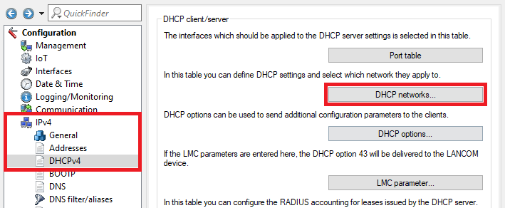
1.8) Switch to the menu IPv4 → DHCPv4 → DHCP networks.
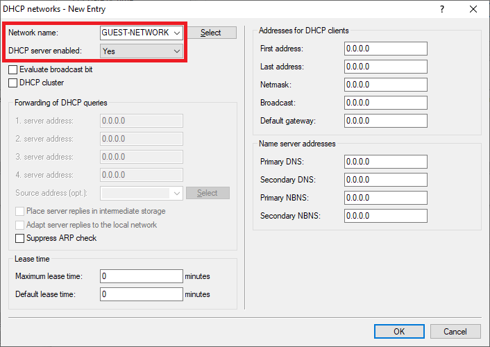
1.9) Create a new entry and adjust the following parameters:
- Network name: From the drop-down menu, select the network created in step 1.7
- DHCP server enabled: From the drop-down menu, select Yes to activate the DHCP server.
If the addresses for the DHCP clients and the name server addresses are all set to 0.0.0.0, the router sets its own IP address as the gateway and DNS server on this network, and it can use all of the free IP addresses on this network for address assignment. You can adjust the individual parameters if necessary.
1.10) This concludes the configuration. Write the configuration back to the router.
2) Differing configuration steps for setting up a guest network on the LAN and Wi-Fi:
The following steps are required in addition to the steps in the chapter 1) Configuring a guest network on the LAN: assuming that Wi-Fi should be made available on the guest network as well as the LAN.
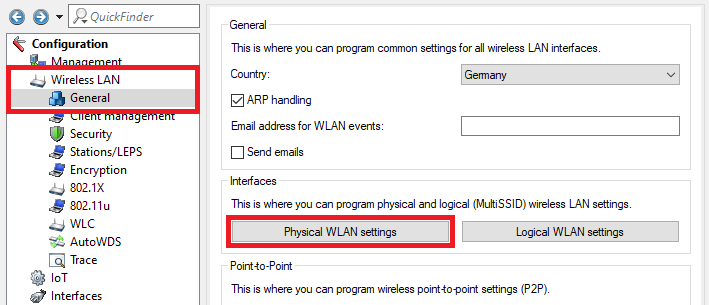
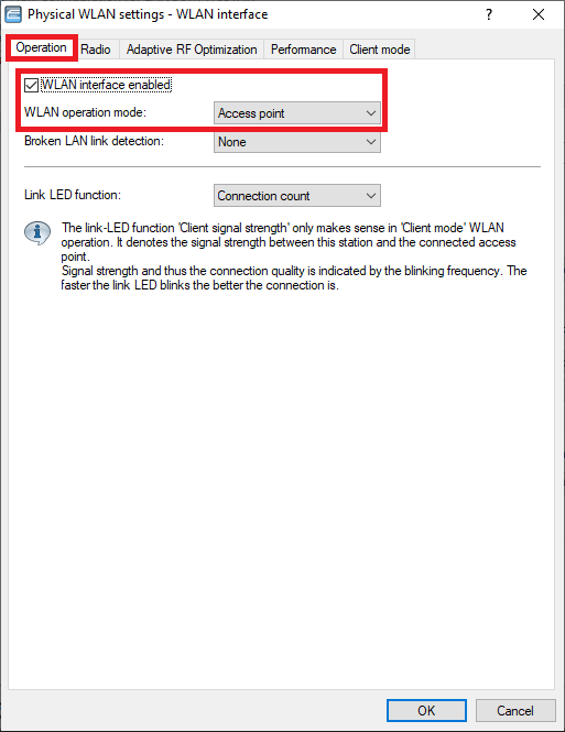
2.1) Switch to the menu Wireless LAN → General → Physical WLAN settings.
2.2) On the Operation tab, modify the following parameters:
- Make sure the checkmark is set for WLAN interface enabled.
- Make sure that the WLAN operation mode is set to Access point
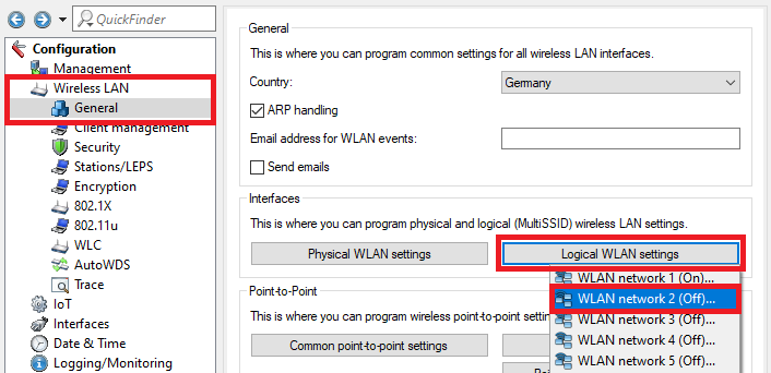
2.3) Change to the menu Logical WLAN settings and select an unused logical WLAN interface (in this example, the WLAN network 2).
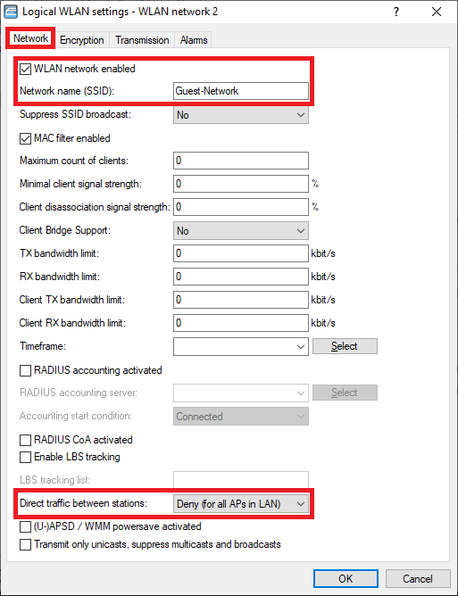
2.4) Enter the following parameters:
- Set a checkmark for WLAN network enabled.
- For the Network name (SSID), enter a meaningful name for the WLAN.
- From the drop-down menu for Direct traffic between stations, select the mode Deny (for all APs in LAN) so that Wi-Fi devices in the guest WLAN cannot communicate with one another.
The feature Data traffic between stations requires the protocol IAPP (Inter Access Point Protocol). If the access point does not support this, this communication cannot be prevented!
IAPP is supported by all LANCOM WLAN routers and access points.
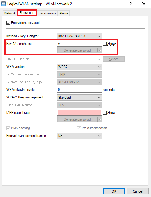
2.5) Change to the tab Encryption and, under Key 1/passphrase, set a WPA key which must be entered on devices wanting to authenticate at the Wi-Fi.
We do not recommend that you operate an unencrypted network without operating a further restriction, such as the Public Spot, otherwise anyone can connect to the Wi-Fi.
2.6) Navigate to the menu Interfaces → LAN → Port table.
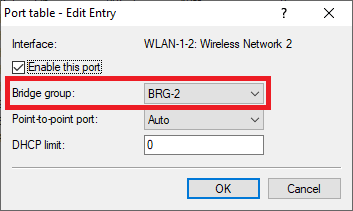
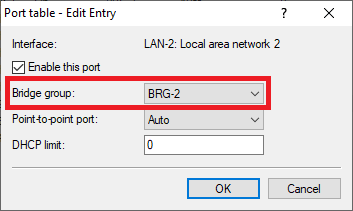
2.7) Assign the interfaces that are to be used for the guest network (see steps 1.2 and 2.3) to a previously unused bridge group (in this case BRG-2).
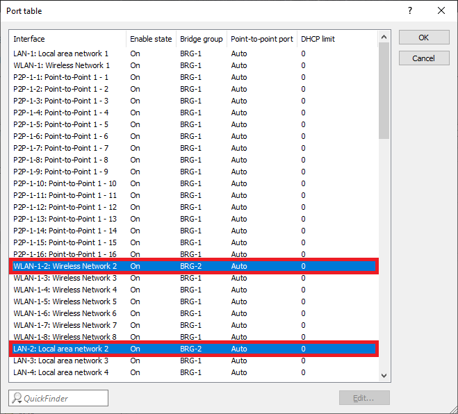
2.8) The Port table should now appear as follows:
2.9) Switch to the menu IPv4 → General → IP networks.
2.10) Edit the Guest network and, under Interface assignment, select the bridge group assigned in step 2.7 (in this example the BRG-2).
2.11) This concludes the configuration. Write the configuration back to the router.