Description:
An N:N mapping is used to connect networks with the same IP address ranges. This translates several IP addresses ("N") from the local network explicitly into several ("N") IP addresses of any other network. This translation prevents an IP address conflict.
The rules for address translation are defined in a static table in the LANCOM router. This involves specifying new IP addresses for individual LAN devices, for subnets or for the whole LAN, which are then used by the devices to communicate with other networks.
Address translation is performed "outbound", i.e. only outgoing connections from the LANCOM device are subject to address translation. Once a connection has been established, data exchange is of course possible in both directions.
"Inbound" address translation for arbitrary incoming connections is not supported. Instead, outbound address translation must be set up on the corresponding remote device.
It is only possible to use networks of the same size for masquerading via N:N mapping. Therefore the networks must have the same subnet mask.
Scenario:
The following example shows how the network configuration below (both LANS are C-class networks) can be connected via VPN: 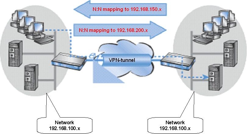
The N:N mapping translates all addresses within the LAN into a new range of addresses for communication with the remote network.
Company A's network is translated to the range 192.168.200.0/24, while company B's network is translated to 192.168.150.0/24. Each LAN is now accessible by the other at these new addresses.
The device being addressed is not located in the local network, so the request is forwarded to the gateway and routed to the remote network, as desired.
Procedure:
1) Set up VPN connections:
First, set up the VPN connections on both routers via the setup wizard. Enter the masked network of the remote site in each case, i.e. the network 192.168.150.0/24 in company A and the network 192.168.200.0/24 in company B (see steps 1.8 and 2.8 in the following Knowledge Base article.)
The procedure to set up an IKEv2 connection via the setup wizard is described in the following Knowledge Base article:
Configuring an IKEv2 VPN connection between two LANCOM routers using the Setup Wizard (IPv4)
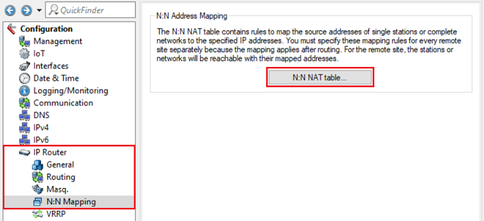
2) Configuring N:N Mapping:
The N:N NAT table is located in the menu IP Router → N:N Mapping → N:N NAT table.
2.1) Configuring N:N mapping on the router in company A:
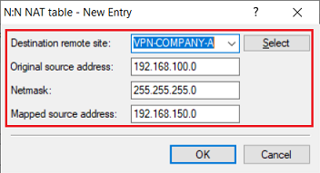
Add a new entry and modify the following parameters:
- Destination remote site: In the dropdown menu select the VPN connection to company B (in this example VPN-COMPANY-B).
- Original source address: Enter the network address of the local network (in this example 192.168.100.0).
- Netmask: Enter the subnet mask assigned to the local network (in this example 255.255.255.0).
- Mapped source address: Enter the network address of an unused network, behind which the local network for the selected remote site is to be masked (in this example 192.168.200.0).

2.2) Configuring N:N mapping on the router in company B:
Add a new entry and modify the following parameters:
- Destination remote site: In the dropdown menu select the VPN connection to company A (in this example VPN-COMPANY-A).
- Original source address: Enter the network address of the local network (in this example 192.168.100.0).
- Netmask: Enter the subnet mask assigned to the local network (in this example 255.255.255.0).
- Mapped source address: Enter the network address of an unused network, behind which the local network for the selected remote site is to be masked (in this example 192.168.150.0).
3) Manual modifications for existing VPN connections (optional):
If the masked networks weren't entered during the setup of the VPN connections (e.g. because the VPN connections had been created beforehand), the routing entries of the VPN connections have to be modified manually.
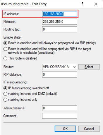
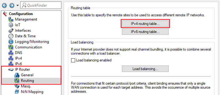
The routing entries are located in the menu IP Router → Routing → IPv4 routing table.
3.1) Modifying the routing entry on the router in company A:
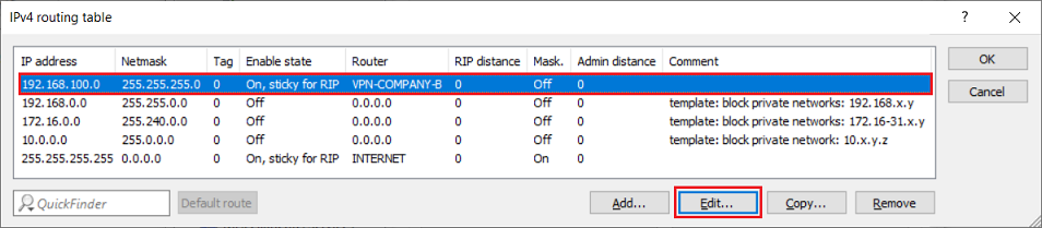
3.1.1) Select the routing entry of the VPN connection and click Edit.
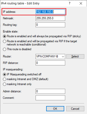
3.1.2) Enter the network address of the masked network of company B in the field IP address (in this example 192.168.150.0).
3.2 Modifying the routing entry on the router in company B:
3.2.1 Select the routing entry of the VPN connection and click Edit.

3.2.2 Enter the network address of the masked network of company A in the field IP address (in this example 192.168.200.0).