Description:
This article describes how static IP parameters can be assigned to an access point with LCOS via the LANCOM Management Cloud (LMC).
Requirements:
- LCOS as of version 10.50 (download latest version)
- Access to the LMC including your own project
- Any web browser for accessing the LMC
Procedure:
1) Allow static IP configuration for access points and switches:
In the LMC, go to the menu item Project specifications and be sure to activate the option Keep static IP configuration for access points and switches.
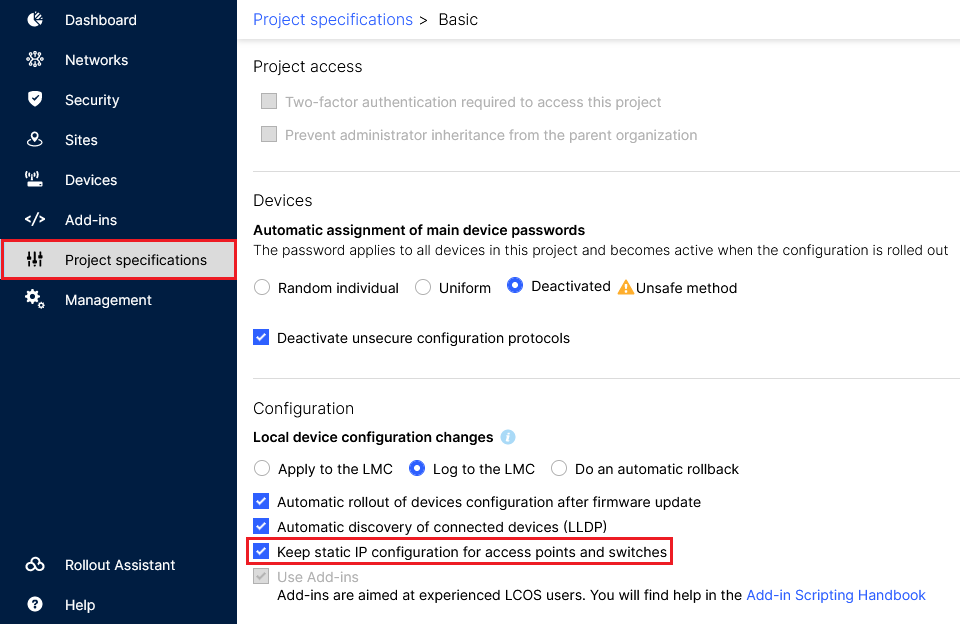 Image of a complex software dashboard with various project specifications, security settings, device configurations, and management tools for technology professionals, including automatic device rollout and configuration options.
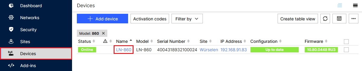
2) Configuring the static IP parameters via the access point’s “Detail configuration”:
2.1) Go to the Detail configuration of the access point:
2.1.1) Go to the Devices menu and click the Name of the relevant access point.
 Screenshot displaying a network management interface, featuring options for adding devices, filtering by various parameters, and tables listing devices with details like model, serial number, site, IP address, and firmware status.
2.1.2) Go to the tab Detail configuration.
 Screenshot of a technical configuration interface with menu options for devices and network settings.
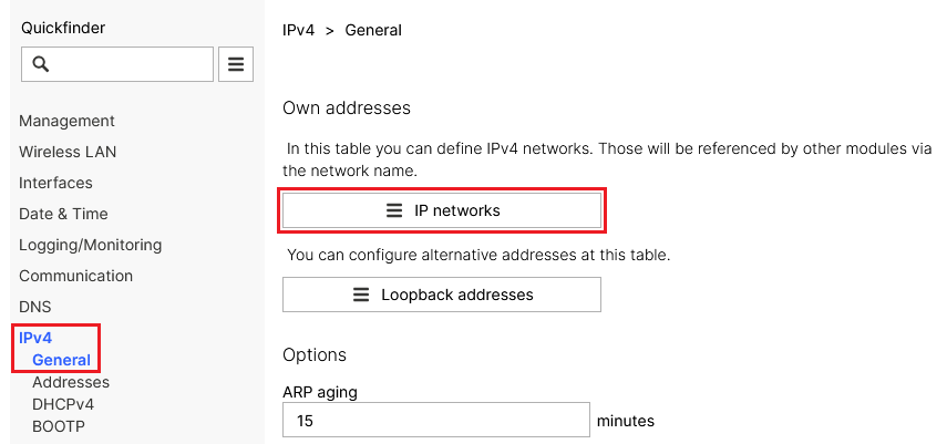
2.2) Setting the IP address and subnet mask:
2.2.1) In the Detail configuration go to the menu IPv4 → General → IP networks.
 Screenshot of a network settings interface showing various configuration options including IP management, Wireless LAN, interfaces, DNS settings, and DHCP options.
2.2.2) Click the Network name for the relevant network to go to the advanced settings.
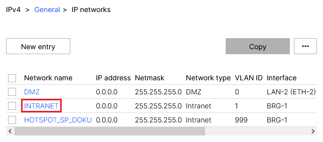 Image depicts a network configuration menu showing network names, IP addresses, netmasks, network types, VLAN IDs, and associated interfaces for various segments including DMZ, LAN, Intranet, and hotspot networks.
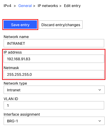
2.2.3) Modify the following parameters and then click Save entry:
- IP address: Enter the IP address the access point should use (in this example 192.168.91.83).
- Netmask: Enter the Netmask for the relevant network (in this example 255.255.255.0).
 Screenshot of a network configuration interface showing settings for an intranet with fields for network name, IP address, netmask, network type, VLAN ID, and interface assignment.
2.3) Disabling the DHCP server:
2.3.1) In the Detail configuration go to the menu IPv4 → DHCPv4 → DHCP networks.
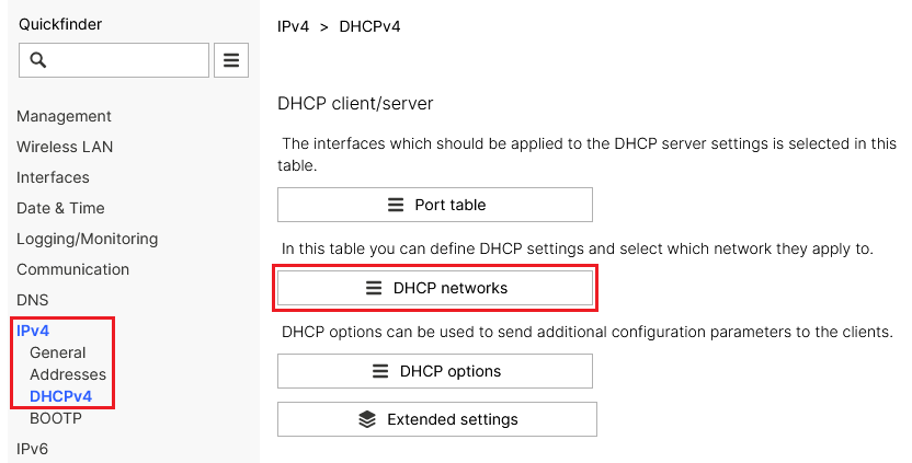 Screenshot of a DHCP management interface showing options for client-server settings, wireless LAN configurations, DHCP networks, DNS settings, and extended IP options.
2.3.2) Click the network name for the network selected in step 2.2.2 to go to the advanced settings.
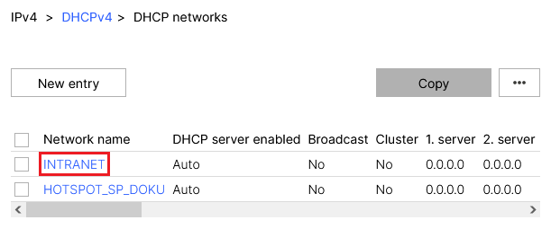 Image displays a network configuration interface showcasing settings for two networks, TINTRANET and HOTSPOTSPDOKU, with columns for network name, DHCP server status, and broadcast cluster settings.
2.3.3) For DHCP server enabled, set the option No and click Save entry.
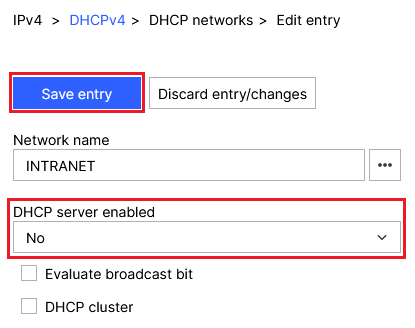 Screenshot of a network configuration menu showing an INTRANET network with DHCP server disabled and options to evaluate the broadcast bit in a DHCP cluster.
2.4) Setting a default route:
2.4.1) In the Detail configuration, navigate to the menu IP Router → Routing → IPv4 routing table.
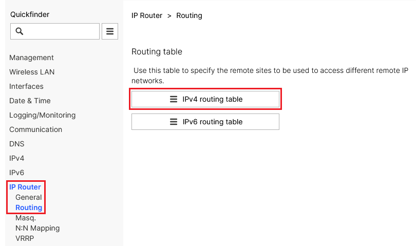 Screenshot of a Quickfinder IPRouter interface showing various networking settings including routing table management, wireless LAN configurations, communication settings like DNS, and monitoring options.
2.4.2) Click the New entry button.
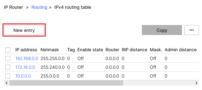 Screenshot of a routing table configuration interface showing columns for IP address, Netmask, Tag, Enable state, Router, RIP distance, Mask, and Admin distance with multiple entries marked as disabled.
2.4.3) Modify the following parameters and then click Save entry:
- IP address: Enter the IP address 255.255.255.255.
- Netmask: Enter the netmask 0.0.0.0.
- Router: Enter the IP address of the default gateway in the access point’s network (in this example 192.168.91.254).
- IP masquerading: Select the option IP masquerading switched off.
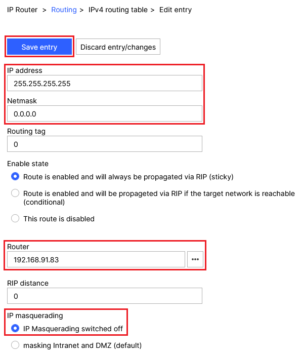 Screenshot of a router configuration interface displaying settings for routing tables, including IP address, netmask, routing tag, RIP propagation rules, and IP masquerading.
2.5) Setting up DNS forwarding:
2.5.1) In the Detail configuration go to the menu DNS → General.
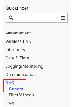 Screenshot of a technical configuration menu with options for management, wireless LAN, interfaces, datetime, logging, and communication settings.
2.5.2) Scroll to the section Host name resolving and go to the menu Forwarding.
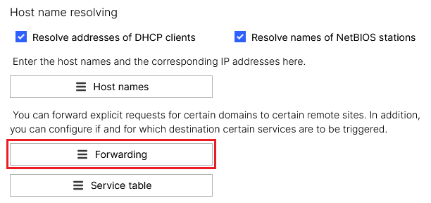 Screenshot of a network configuration interface showing options for resolving hostnames, DHCP client addresses, NetBIOS station names, and setting up domain-specific remote site forwarding and service triggers.
2.5.3 Klicken Sie auf die Schaltfläche New entry.
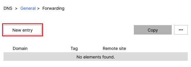 Screenshot of a DNS General Forwarding configuration interface displaying the Domain Tag for a Remote site with no elements found.
2.5.4) Modify the following parameters and then click Save entry:
- Domain: Enter the wildcard *. This represents any number of characters.
- Remote site: Enter the IP address of a DNS server that should resolve DNS requests from the access point (in this example the IP address of the default gateway 192.168.91.254).
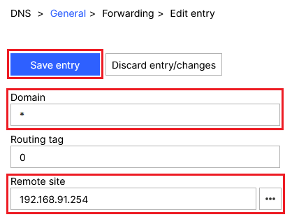 Screenshot of a DNS General Forwarding Edit entry interface with options for Routing Tag and Remote Site configurations.
3) Rolling out the configuration to the access point:
3.1) In the LMC, go to the menu Devices and, under Configuration for the relevant access point, click Outdated.
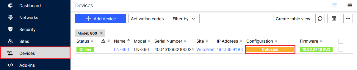 Screenshot of a technical dashboard interface showing options for network devices, activation codes, and device security settings with tables detailing device status, model, and firmware updates.
3.2) Finally, implement the changes by clicking Roll out.
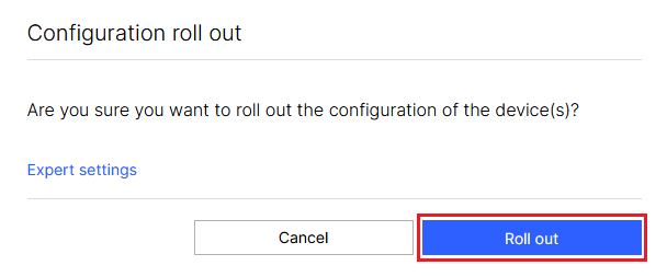 Confirmation dialog box on a computer screen asking whether to proceed with rolling out configuration settings for devices, with an option to select 'Expert settings' or 'Cancel'.
