
Description:
This document describes how to configure a vpn load balancer operating two VPN connections that are divided between two WAN connections, as required by the load. This configuration example is adaptable for more than two WAN connections.
Requirements:
- LCOS as of version 10.12 (download latest version)
- LANtools as of version 10.12 (download latest version)
Scenario:
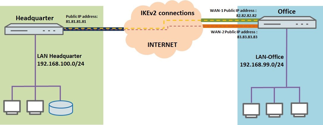
- A link is to be established between a branch office and the headquarters based on two IKEv2 site-to-site VPN connections using VPN load balancing to spread the load of the data traffic between them.
- The branch office has two WAN connections, which should be used for WAN load balancing and also for VPN load balancing.
- All of the LANCOM routers in the following scenarios have at least a basic configuration and can be reached in their respective LAN (or via the WAN).
- The required WAN connections are already operational at both ends.
Procedure:
1) Configuring IKEv2 connections and VPN load balancing on the branch office router:
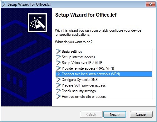
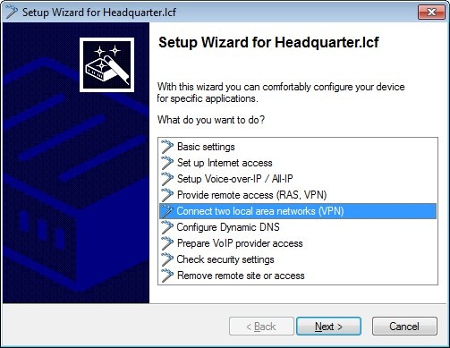
1.1) Open the Setup Wizard on the LANCOM router at the branch office and select Connect two local area networks (VPN).
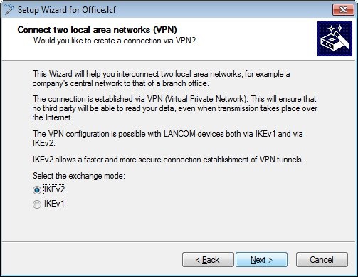
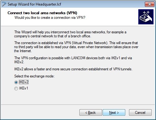
1.2) In the next dialog, select the exchange mode IKEv2.
1.3) In this example, we do not use IPSec-over-HTTPS.

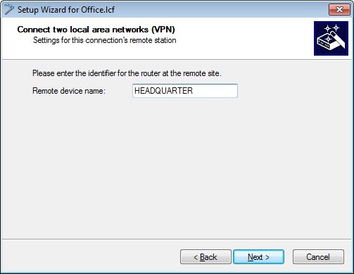
1.4) In the next dialog, enter the name of the LANCOM router at the remote site. In this example it is HEADQUARTER.
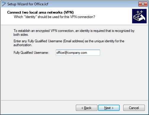
1.5) To establish an encrypted VPN connection, we need an identity that is known to both sites.
In this example, the identity is the e-mail address office@company.com.
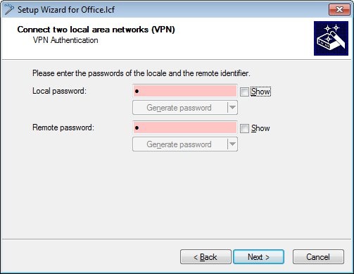
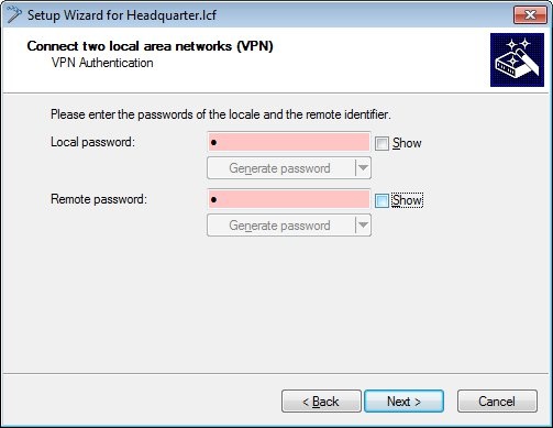
1.6) Create passwords for the local and the remote identity.
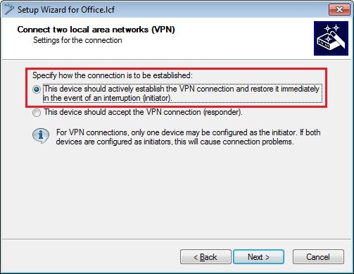
1.7) Since the LANCOM router at the branch office should establish the VPN connection to the headquarters, you need to choose the upper option.
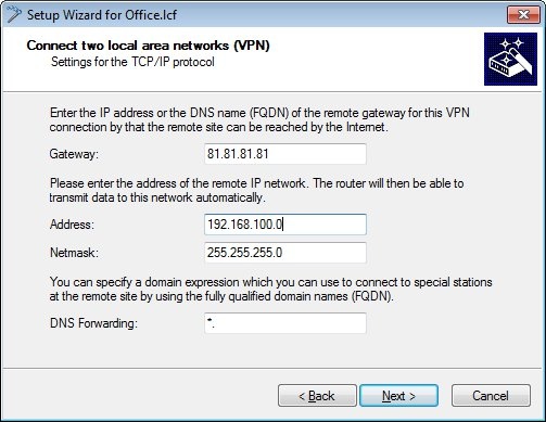
1.8) The gateway needs to be set to the public IP address (or the DNS name) of the LANCOM router at the headquarters.
Because the local network in the headquarters has the address range 192.168.100.0/24, this need to be entered into the fields Address and Netmask.
1.9) Click on Finish to close the Wizard and write the configuration back to the LANCOM router.

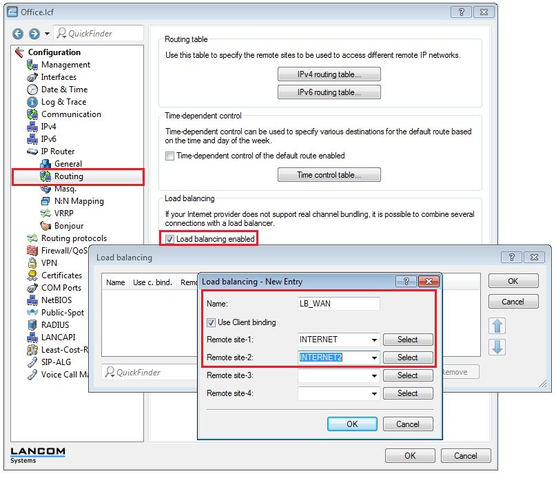
1.10) Open the configuration for the LANCOM router, switch to the menu item IP router → Routing and enable load balancing.
1.11) Create a new entry for WAN load balancing with the name LB_WAN and two WAN remote sites INTERNET and INTERNET2.
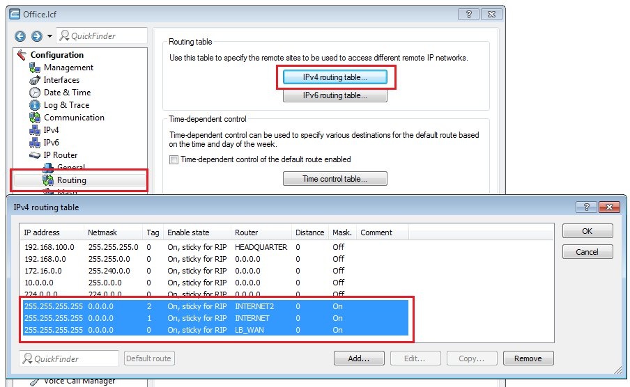
1.12) Navigate to the menu IP router → Routing → IPv4 routing table.
- Configure the default routes for the two Internet connections and the WAN load balancer as shown in the following figure
Each of the two Internet connections receives its own routing tag in order to bind a VPN tunnel to an Internet connection.
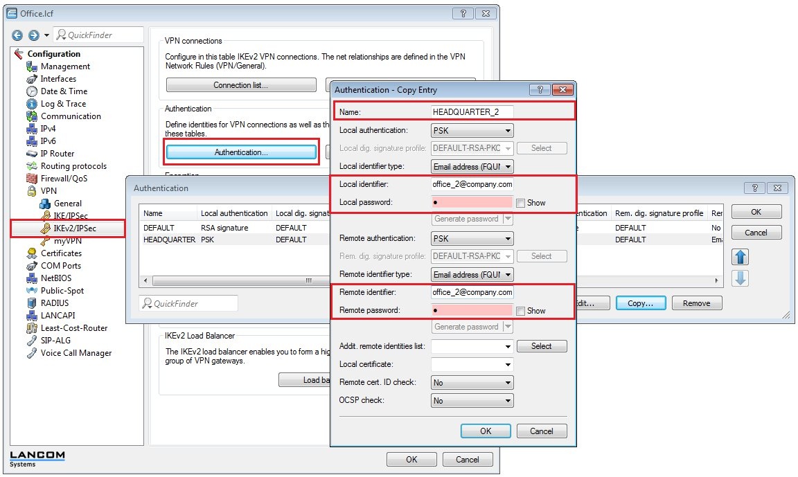
1.13) Switch to the menu VPN → IKEv2/IPSec → Authentication.
- Select the entry for the headquarters and click on Copy.
- Change the name of the new entry to HEADQUARTER_2, for example.
- Change the e-mail address of local and remote identities to office_2@company.com.
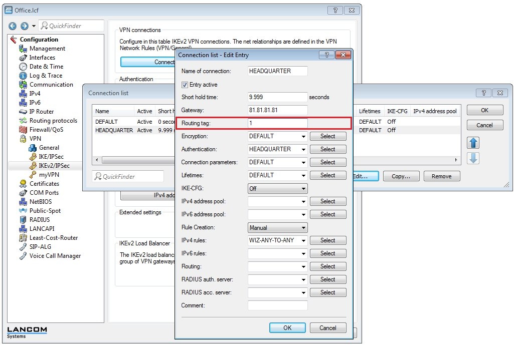
1.14) Switch to the menu VPN → IKEv2/IPSec → Connection list.
- Choose the entry for the headquarters.
- Set the routing tag to 1 (routing tag of the first WAN connection, see step 1.12).
- Close the dialog with OK.
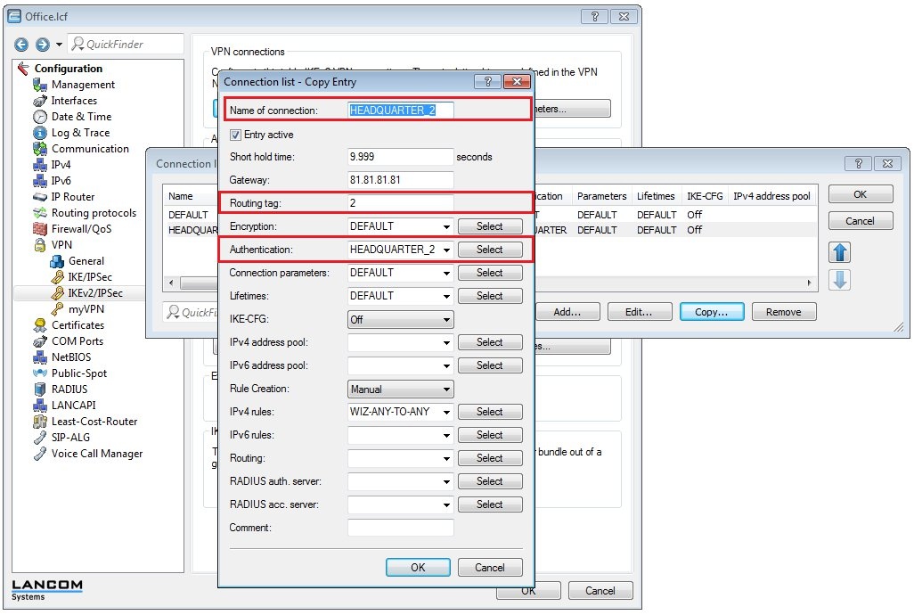
- Select the entry for the headquarters and click on Copy.
- Change the name of the new entry to HEADQUARTER_2, for example.
- Set the routing tag to 2 (routing tag of the second WAN connection, see step 1.12).
- Switch the Authentication to the entry HEADQUARTER_2 (see step 1.13).
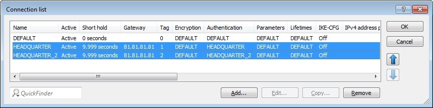
1.15) The entries in the connection list must then be configured as shown in the following figure.
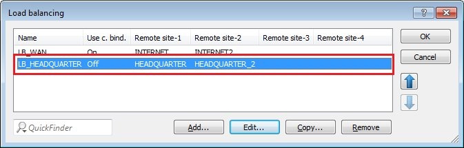
1.16) Navigate to the menu IP Router → Routing → Load balancing and create a new entry with the name LB_HEADQUARTER and the two IKEv2 VPN remote sites HEADQUARTER and HEADQUARTER_2.
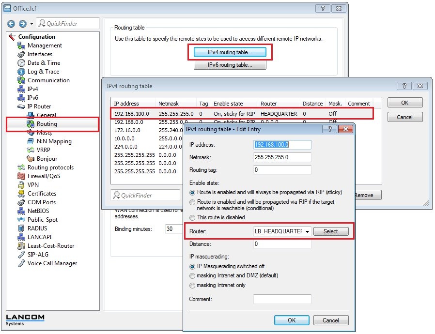
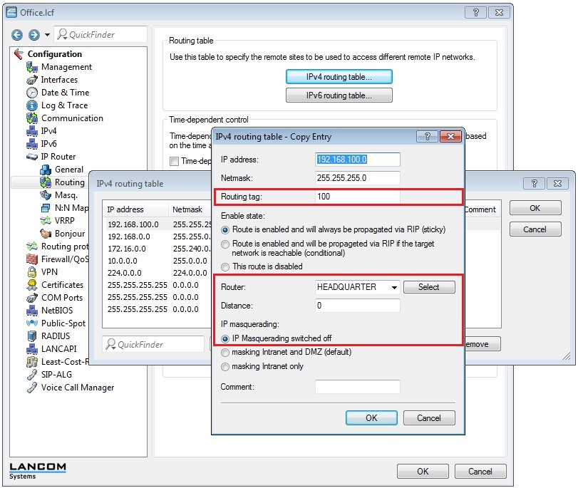
1.17) Navigate to the menu IP router → Routing → IPv4 routing table.
- Select the entry for the Headquarters and click on Edit.
- Select the load balancer remote site LB_HEADQUARTER.
- Switch IP masquerading off.
- Close the dialog with OK.
- Select the entry for the Headquarters and click on Copy.
- Assign a previously unused routing tag.
- Select the VPN remote site HEADQUARTER.
- Switch IP masquerading off.
- Close the dialog with OK.
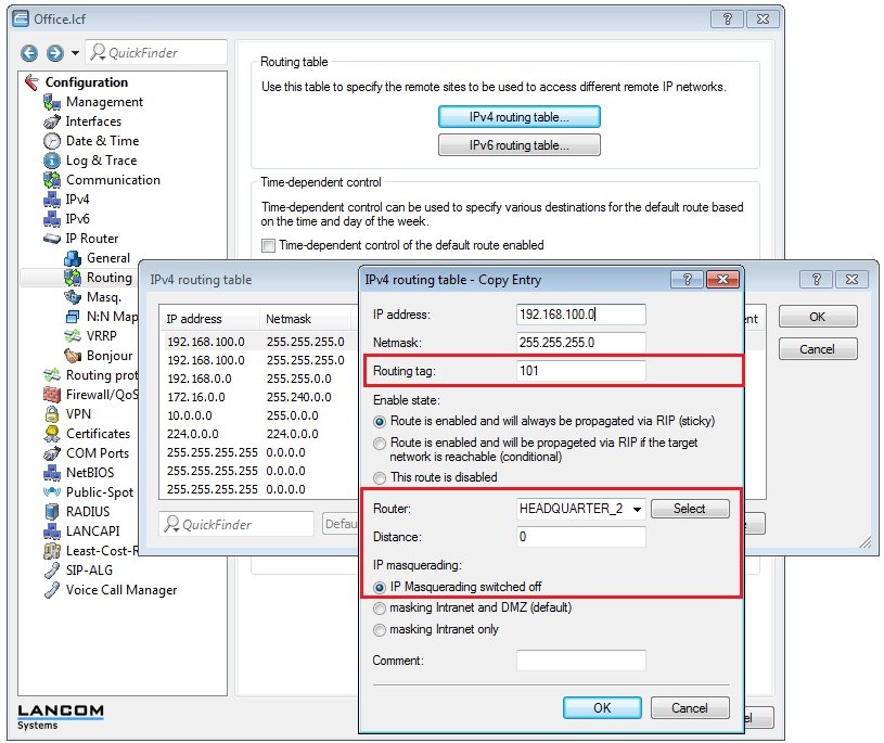
- Select the entry for the Headquarters again and click on Copy.
- Assign a previously unused routing tag.
- Select the VPN remote site HEADQUARTER_2.
- Switch IP masquerading off.
- Close the dialog with OK.
1.18) Close the dialog with OK and write the configuration back to the LANCOM router.
2) Configuring IKEv2 connections and VPN load balancing on the router at the headquarters:
2.1) Open the Setup Wizard on the LANCOM router at the headquarters and select Connect two local area networks (VPN).
2.2) In the next dialog, select the exchange mode IKEv2.
2.3) In this example, we do not use IPSec-over-HTTPS.

2.4) In the next dialog, enter the name of the LANCOM router at the remote site. In this example it is OFFICE.

2.5) To establish an encrypted VPN connection, we need an identity that is known to both sites.
In this example, the identity is set to the e-mail address office@company.com (this identity must match the one specified in step 1.5).

2.6) Create passwords for the local and the remote identity. These must match the passwords set in step 1.6).
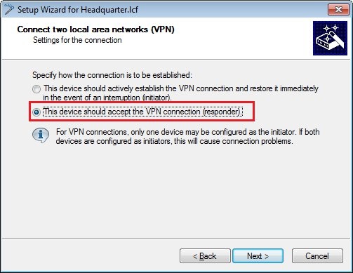
2.7) Since the LANCOM router at the headquarters should receive the VPN connection from the branch office, you need to choose the lower option.
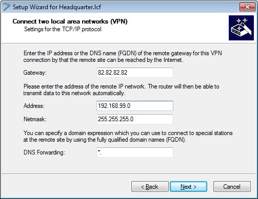
2.8) The gateway needs to be set to the public IP address (or the DNS name) of the first WAN connection at the branch office.
Because the local network in the branch office has the address range 192.168.99.0/24, this needs to be entered into the fields Address and Netmask.
This configuration example uses fixed public IP addresses at the branch office. How to set up the VPN connection when the branch office uses dynamic IP addresses is described in this Knowledge Base article.
2.9) Click on Finish to close the Wizard and write the configuration back to the LANCOM router.

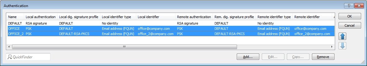
2.10) Open the the LANCOM router configuration and navigate to VPN → IKEv2/IPSec → Authentication.
- Select the entry for the branch office and click on Copy.
- Change the name of the new entry to OFFICE_2, for example.
- Change the e-mail address of local and remote identities to office_2@company.com. The e-mail address entered here must match the address given in step 1.13.
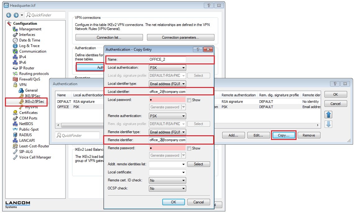
2.11) The authentication rules must then be configured as shown in the following figure.
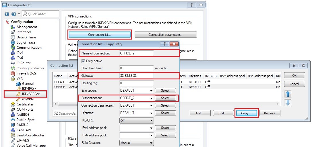
2.12) Switch to the menu VPN → IKEv2/IPSec → Connection list.
- Select the entry for the branch office and click on Copy.
- Change the name of the new entry to OFFICE_2, for example.
- Set the remote gateway to the public IP address (or the DNS name) of the second WAN connection of the LANCOM router at the branch office. If the branch office uses dynamic public IP addresses this field must be left blank.
- Switch the Authentication to the entry OFFICE_2 (see step 2.10).
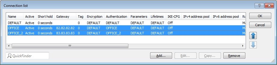
2.13) The entries in the connection list must then be configured as shown in the following figure.
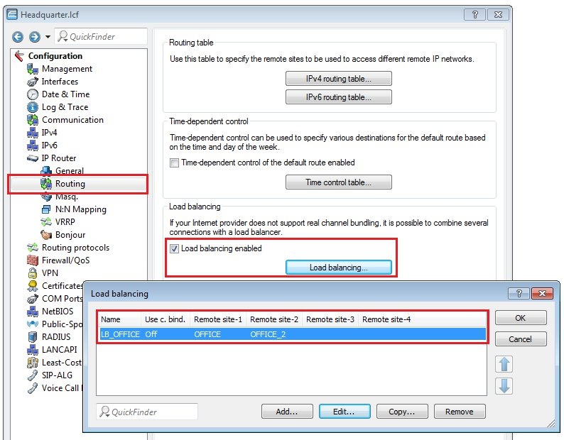
2.14) Navigate to the menu IP router → Routing and enable the load balancing.
2.15) Create a new entry with the name LB_OFFICE and the two IKEv2 VPN remote stations OFFICE and OFFICE_2.
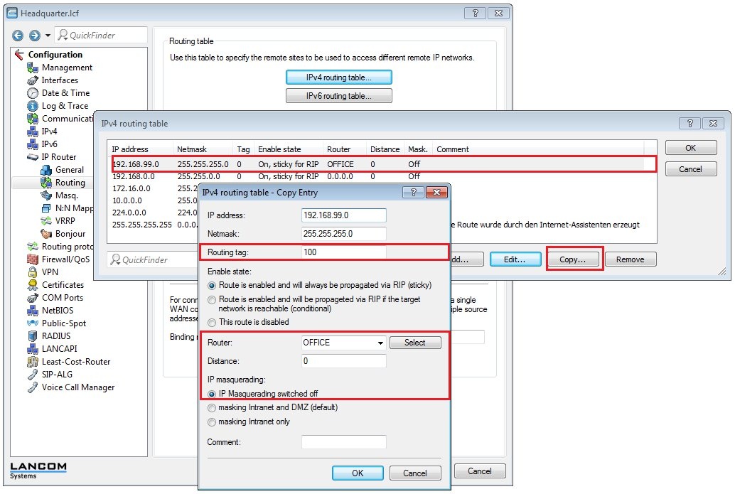
2.16) Navigate to the menu IP router → Routing → IPv4 routing table.
- Select the entry for the branch office and click on Copy.
- Assign a previously unused routing tag.
- Select the VPN remote site OFFICE.
- Switch IP masquerading off.
- Close the dialog with OK.
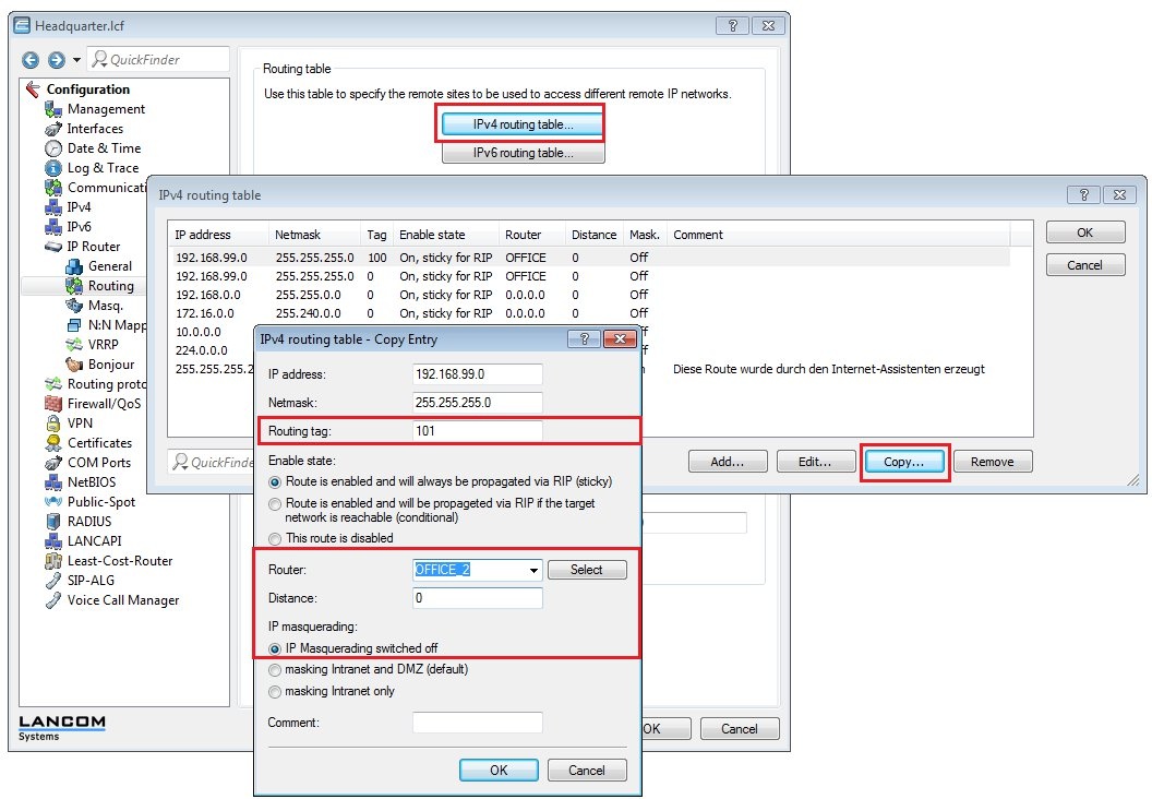
- Select the entry for the office again and click on Copy.
- Assign a previously unused routing tag.
- Select the VPN remote site OFFICE_2.
- Switch IP masquerading off.
- Close the dialog with OK.
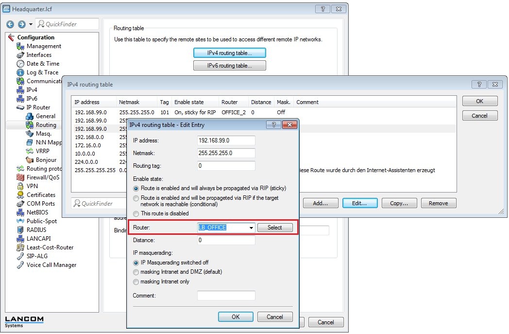
- Select the entry for the office again and click on Copy.
- Select the load balancer remote site LB_OFFICE.
- Switch IP masquerading off.
- Close the dialog with OK.
2.17) Close the dialog with OK and write the configuration back to the LANCOM router.
2.18) This concludes the configuration.