Description:
A WLAN controller manages access points and assigns them the WLAN parameters they need to operate. If the WLAN controller also functions as a gateway (for example when operating as a Public Spot) or it operates a WLC tunnel, the WLAN controller represents a “single point of failure”.
In a scenario like this, having at least one additional WLAN controller for redundancy is an advantage. You can configure load balancing so that the access points are distributed between the WLAN controllers. Furthermore, one WLAN controller can be configured as a standby unit, so that if a problem occurs, the access points connect to the second standby WLAN controller as soon as the first one fails.
A change of WLAN controller interrupts all ongoing sessions (when operating as a gateway). These have to be reestablished by the end devices.
In particular when operating as a Public Spot, please note that the user information, such as the accrued online time, is not transferred to other WLAN controllers. The online time for Public Spot users basically begins anew.
- When using this Clustering solution no configuration synchronisation is done by the WLAN Controllers (HA Cluster). To synchronize the configuration the " LANCOM High Availability Clustering Option" is needed on both WLAN Controllers. Informations regarding the configuration of such a scenario can be found in the Knowledge Base article Setting up a WLC cluster with the Setup Wizard.
Requirements:
- LCOS as of version 9.0 (download latest Version)
- LANtools as of version 9.0 (download latest Version)
- The second WLAN Controller (Slave) must must be unconfigured and still with its factory settings!
- The option Certificate authority (CA) active in the menu Certificates → Cert. authority (CA) on the second WLAN Controller (Slave) must not be active!
Scenario:
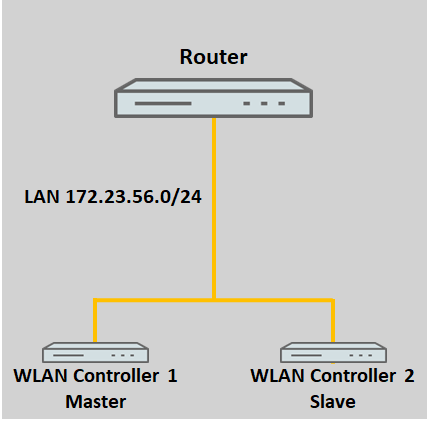
1) Both WLAN controllers are in the same network:
If the WLAN controllers are both in the same network, they will discover one another automatically by broadcast.
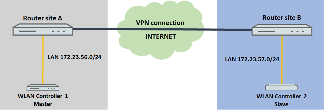
2) The two WLAN controllers are in different networks:
If the WLAN controllers are in different networks, the IP addresses of the WLAN controllers must be made known to one another manually.
Usually, the WLAN controllers will be located at different locations in a scenario like that pictured below. It is also conceivable that the WLAN controllers are at the same location but in separate networks.
Procedure:
The configuration of the WLC cluster is basically the same for both scenarios. The only difference is the way that the other WLC cluster member is announced (see step 3.).
When using the table "Access stations" in the menu Management → Admin → Access settings → Configuration access ways the IP address (e.g. IP address 192.168.1.1 Netmask 255.255.255.255) or the whole network of the other WLAN Controller (e.g . IP address 192.168.1.0 Netmask 255.255.255.0) has to be entered in the table in order for the devices to be able to communicate with each other!
The option WLC data tunnel active in the menu WLAN Controller → General must not be activated on any of the devices!
1) Configuring the first WLAN controller (master):
1.1) Perform the basic setup of the WLAN controller as described in this knowledge base article.
1.2) Then configure the WLAN profiles as required. Here are two examples:
- WLAN layer-3 tunneling tutorial: WLAN controller with Public Spot
- Manually configuring a guest network on a WLAN controller by means of VLAN
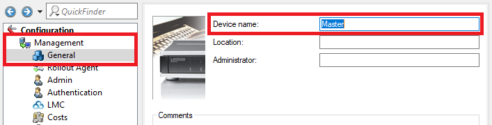
1.3) Change to the menu Management → General and set a descriptive Device name.
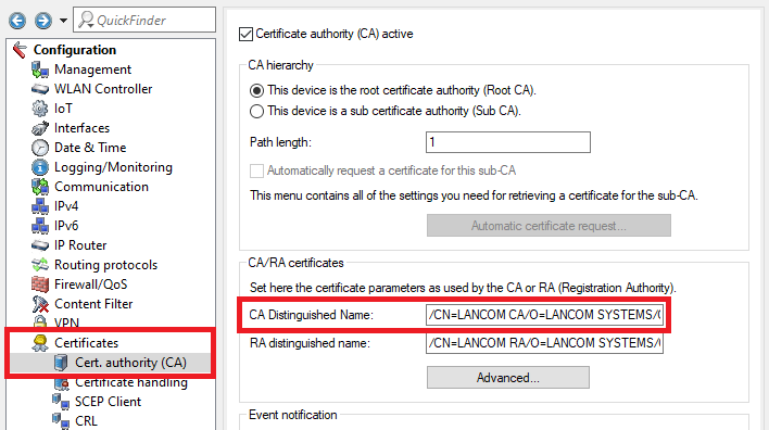
1.4) Go to the menu Certificates → Cert. authority (CA) and save the CA Distinguished Name for later use.
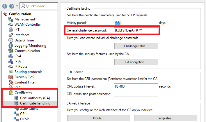
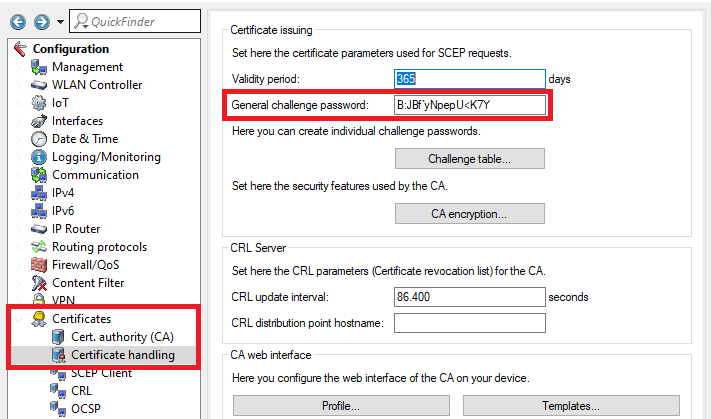
1.5) Open the menu Certificates → Certificate handling and save the General challenge password for later use.
1.6) The configuration of the first WLAN controller is now complete.
2) Configuring the second WLAN controller (slave):
The second WLAN controller must be unconfigured and still with its factory settings!
2.1) Save the configuration of the first WLAN controller as a script file.
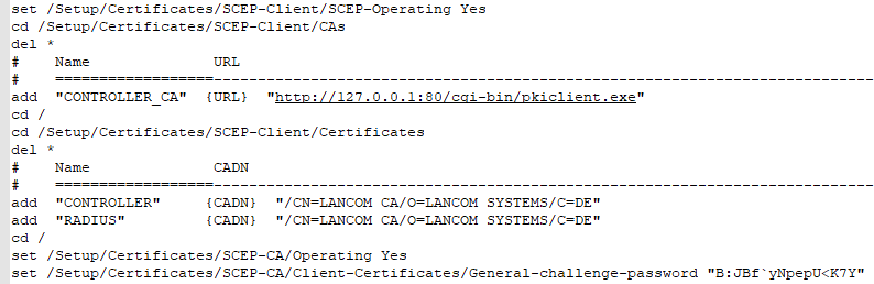
2.2) Open the script backup in a text editor and edit the following items:
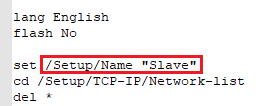
- Navigate in the path Setup/Name and adjust the Device name.
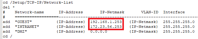
- Navigate to the path Setup/TCP-IP/Network-list and adjust the IP addresses of all networks so that each WLAN controller has been assigned a unique IP address.
- Delete all entries in the path Setup/Certificates.
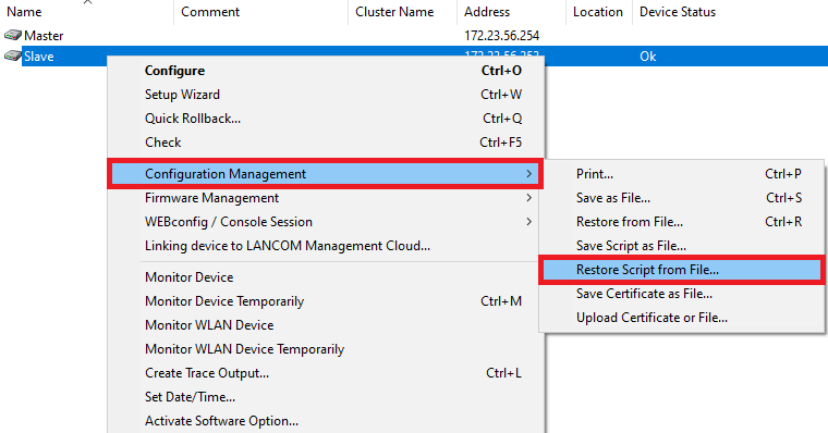
2.3) Upload your customized script backup to the second WLAN controller: Right-click on the slave WLAN controller and, in the context menu, click Configuration management → Restore script from file.
Alternatively you can use LANconfig and drag & drop the script file from your folder onto the WLAN controller.
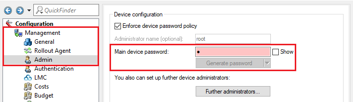
2.4) Change to the menu Management → Admin and set a Main device password.
The Main device password is not included in a script backup, so it has to be set manually afterwards.
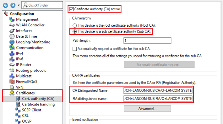
2.5) Change to the menu Certificates → Cert. authority (CA) and modify the following parameters:
- Set a checkmark next to Certificate authority (CA) active.
- Select the radio button This device is a sub certificate authority (Sub-CA).
- Adjust the Common Name (CN) of the CA Distinguished Name (i.e. /CN=LANCOM-SUB).
- Adjust the Common Name (CN) of the RA Distinguished Name (i.e. /CN=LANCOM-SUB).
2.6) Change to the menu Certificates → Certificate handling and enter the General challenge password of the master WLAN controller (see step 1.5).
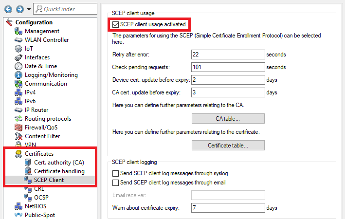
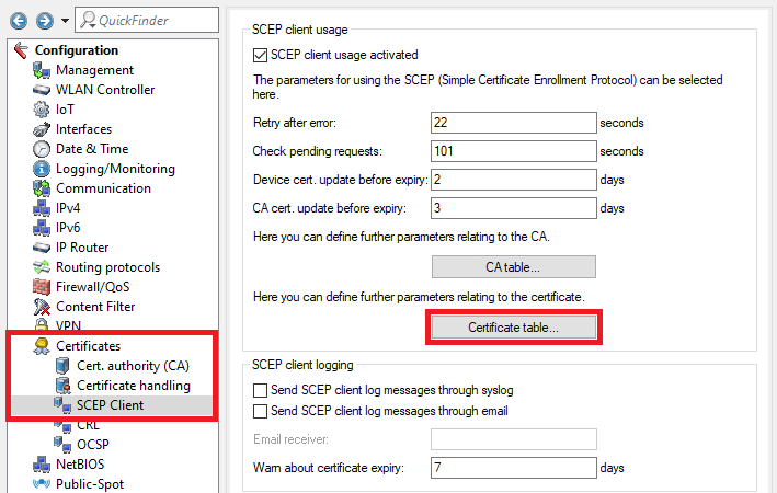
2.7) Go to the menu Certificates → SCEP client and set a checkmark next to SCEP client usage activated.
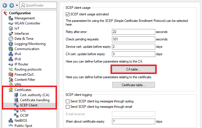
2.8) Go to the menu CA table.
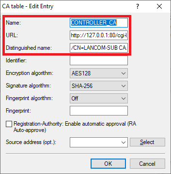
2.9) Two entries have to be created in the CA table. One entry serves to obtain a controller certificate from the device’s own certificate authority and the second entry serves to obtain the CA from the master WLAN controller.
Create the first entry and adjust the following parameters:
- Name: Enter a descriptive name (in this example CONTROLLER_CA).
- URL: Enter the URL http://127.0.0.1:80/cgi-bin/pkiclient.exe .
- Distinguished name: Enter the CA distinguished name of the slave WLAN controller (see step 2.5).
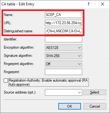
Create the second entry and adjust the following parameters:
- Name: Enter a descriptive name (in this example SCEP_CA).
- URL: Enter the URL http://172.23.56.254/cgi-bin/pkiclient.exe . If necessary, change the IP address 172.23.56.254 to the IP address of the master WLAN controller.
- Distinguished name: Enter the CA distinguished name of the master WLAN controller (see step 1.4).
2.10) Go to the menu Certificate table.
2.11) Three entries have to be created in the certificate table. These specify more detailed information for individual certificates, such as the Key length and Subject. This is necessary so that certificates with the required characteristics can be created and obtained.
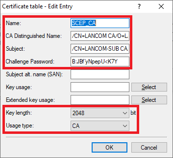
Create the first entry and adjust the following parameters:
- Name: Enter a descriptive name (in this example SCEP_CA).
- CA distinguished name: Enter the CA distinguished name of the master WLAN controller (see step 1.4).
- Subject: Set the subject as the CA distinguished name of the slave WLAN controller (see step 2.5).
- Challenge password: Enter the challenge password of the master WLAN controller (see step 1.5).
- Key length: From the drop-down menu, select 2048.
- Usage type: From the drop-down menu, select CA.
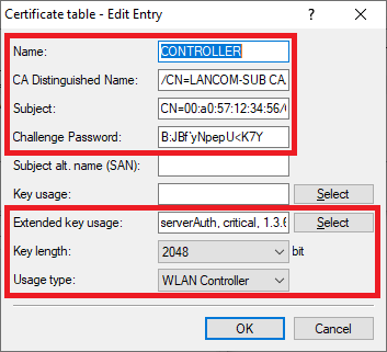
Create the second entry and adjust the following parameters:
- Name: Enter a descriptive name (in this example CONTROLLER).
- CA distinguished name: Enter the CA distinguished name of the slave WLAN controller (see step 2.5).
- Subject: Set the Subject to CN=00:a0:57:12:34:56/O=LANCOM SYSTEMS/C=DE, where the MAC address 00:a0:57:12:34:56 should be replaced by the MAC address of the slave WLAN controller.
- Challenge password: Enter the challenge password of the master WLAN controller (see step 1.5).
- Extended key usage: In the selection menu, set check marks for the options serverAuth, critical and 3.6.1.5.5.7.3.18.
- Key length: From the drop-down menu, select 2048.
- Usage type: From the drop-down menu, select WLAN controller.
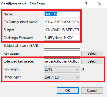
Create the third entry and adjust the following parameters:
- Name: Enter a descriptive name (in this example RADIUS).
- CA distinguished name: Enter the CA distinguished name of the slave WLAN controller (see step 2.5).
- Subject: Set the Subject to /CN=RADIUS SERVER/O=LANCOM SYSTEMS/C=DE.
- Challenge password: Enter the challenge password of the master WLAN controller (see step 1.5).
- Extended key usage: In the selection menu, set check marks for the options serverAuth, clientAuth and critical.
- Key length: From the drop-down menu, select 2048.
- Usage type: From the drop-down menu, select EAP/TLS.
2.12) This concludes the configuration of the slave WLAN controller. You can now write the configuration back to the device.
3) Activate the WLC cluster and announce the other WLC cluster members:
The steps described in the following must be performed on both WLAN controllers. The configuration differs depending on whether the WLAN controllers are in the same network or in different networks.
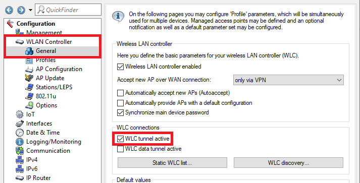
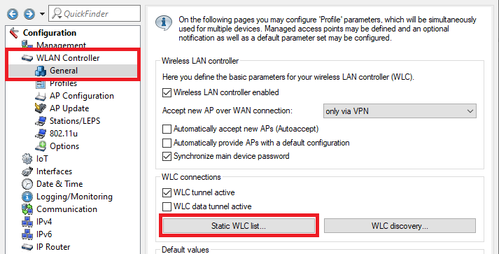
Change to the menu WLAN controller → General and enter a check mark for WLC tunnel active to activate the WLC cluster.
The option WLC data tunnel active must not be activated!
3.1) Both WLAN controllers are in the same network:
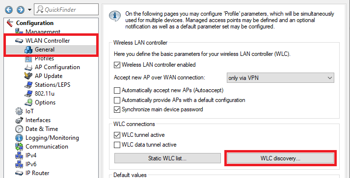
3.1.1) Switch to the menu WLC discovery.
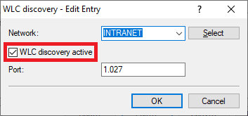
3.1.2) Set the management network where the two WLAN controllers are located and check the box WLC discovery active. This enables the WLAN controllers to use a broadcast to find one another in the local network.
Info:
If you use a different management network, add this and activate the WLC search for this network.
3.2) The two WLAN controllers are in different networks:
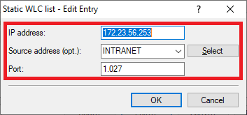
3.2.1) Navigate to the menu WLAN controller → General → Static WLC list.
3.2.2) Create a new entry and modify the following parameters:
- IP address: Enter the IP address of the other WLAN controller.
- Source address (opt.): Use the drop-down menu to select the management network.
- Port: Enter port 1027.