...
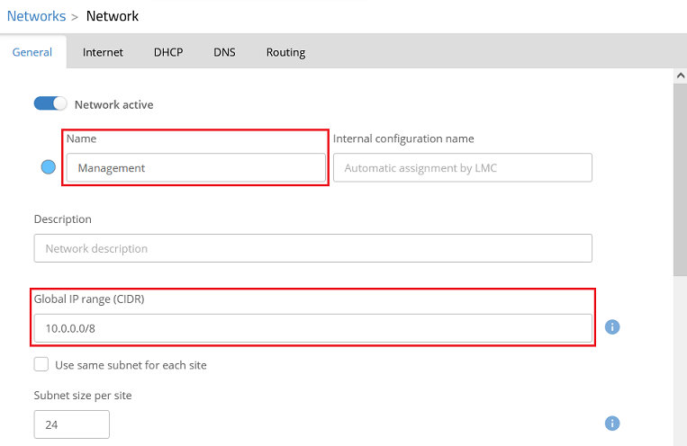
- The network named Management is to be created with the IP address range 10.0.0.0/24. This is operated “untagged” and thereby implicitly uses the VLAN ID 1.
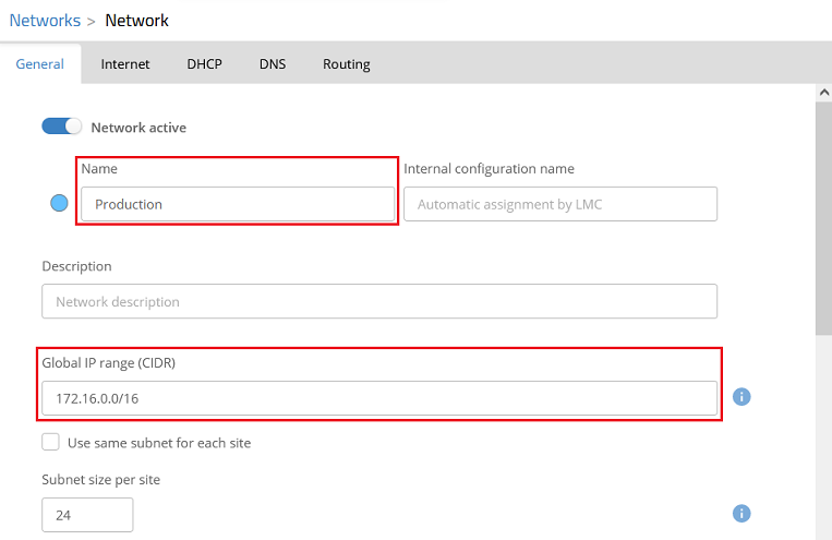
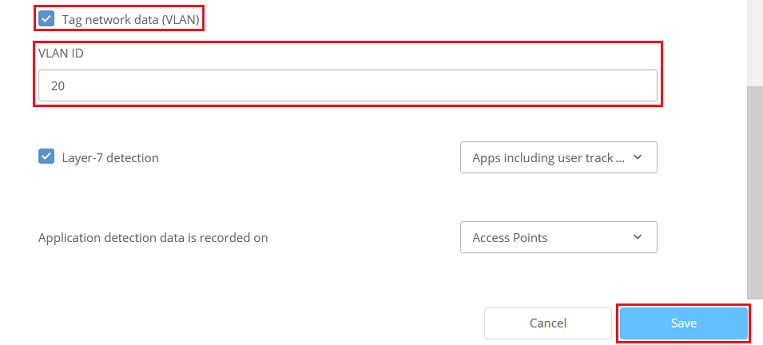
- The network named Production is to be created with the IP address range 172.16.0.0/24. This is assigned the VLAN ID 20.
Procedure:
1) Creating the networks and adjusting the network settings for the switches:
...
1.11) Connect to the LMC, navigate to the menu Networks and click Add Network → Network.
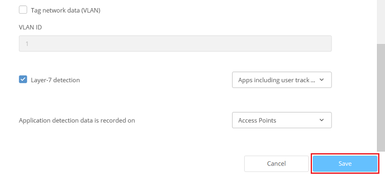
1.1.2) Modify the following parameters and then click Save to create a management network.
...
| Hinweis |
|---|
Since LANCOM switches in the factory state always use the management VLAN 1, they can no longer be managed by the LMC if a different VLAN ID is used. For this reason, the option Tag network data (VLAN) cannot be activated for the management network. In other words the network must operate “untagged”. This can only be changed in the LMC using an add-in script, which is not covered in this article. |
1.1.3) Create another network by clicking Add Network → Network. Modify the following parameters and then click Save to create a productive network.
- Name : Enter a descriptive name for the productive network (in this example Production).
- Global IP range (CIDR) : If necessary, enter the global IP address range for the intermediate network in CIDR notation (Classless Inter Domain Routing).
- Tag network data : Activate this option to enable the VLAN.
- VLAN ID : Enter the VLAN ID that this network should use (in this example, VLAN ID 20).
1.2) Adapting the network specifications for the switches:
...


