Versionen im Vergleich

Schlüssel

  • Diese Zeile wurde hinzugefügt.
  • Diese Zeile wurde entfernt.
  • Formatierung wurde geändert.
Seiteneigenschaften


Description:

This document describes how to configure a LANCOM R&S® Unified Firewall for stand-alone operation.


Requirements:
  • Web browser for configuring the Unified Firewall.

    The following browsers are supported:
    • Google Chrome
    • Chromium
    • Mozilla Firefox
  • Internet access via upstream provider router or DSL/cable modem


Scenario:

The scenario described in this document is also known as stand-alone operation.
  • The Unified Firewall is connected directly to the router or DSL/cable modem from your provider.
  • On interface eth0 of the Unified Firewall, a WAN connection is created to the provider router or DSL/cable modem.
  • The productive network is on the interface eth1 on the Unified Firewall. This then provides all services on the network (such as DHCP) and also acts as the default gateway.
Image Removed

Image Added

The stand-alone operation described here has the following advantages and disadvantages:
Image Removed

Image Added


Procedure:

1) Setting up the Internet connection:

1.1) Internet connection via provider router with static address assignment (e.g. cable Internet or SDSL):

1.1.1) Open the configuration interface of the Unified Firewall in your browser, change to the menu Network -> Connections -> Network Connections and click on the chevron icon to enter the advanced view.
Image Removed

Image Added

1.1.2) Delete the entry for the interface eth0.
Note:
  • By default the interface
eth0
  • is set to
DHCP
  • .
Image Removed

Image Added

1.1.3) Click on the “+” icon to create a new connection.
Image Removed

Image Added

1.1.4) Modify the following parameters:
  • Name: Enter a descriptive name.
  • Interface: From the drop-down menu, select the interface eth0.
  • Type: Check that the value is set to Static.
  • IP Addresses: Enter the IP address assigned by the provider along with the subnet mask. This has to be entered in CIDR notation (Classless Inter-Domain Routing) (e.g. 81.81.81.2/29).
Image Removed

Image Added

1.1.5) Change to the WAN tab and modify the following parameters:
  • Set a checkmark next to Set default gateway.
  • Default Gateway: Enter the provider router’s IP address, which you have received from your provider.
Image Removed

Image Added


1.2) Internet connection via provider router with dynamic address assignment per DHCP (e.g. cable Internet or SDSL):

1.2.1) Navigate to the menu Network -> Connections -> Network Connections and edit the entry for the interface eth0.
Image Removed

Image Added

1.2.2) Modify the following parameters:
  • Name: Enter a descriptive name.
  • Set a checkmark next to Obtain Gateway.
  • Set a checkmark next to Obtain DNS Server.
  • Set a checkmark next to Obtain Domain.
Image Removed

Image Added


1.3) Internet connection via DSL modem (PPPoE):

1.3.1) Navigate to the menu Network -> Connections -> Network Connections and delete the entry for the interface eth0.
Info:
  • By default the interface
eth0
  • is set to
DHCP
  • .
Image Removed

Image Added

1.3.2) Navigate to the menu Network -> Interfaces -> PPP Interfaces and click on the “+” icon to create a new one PPP interface.
Image Removed

Image Added

1.3.3) From the drop-down menu Master Interface, select the interface eth0.
Image Removed

Image Added

1.3.4) Change to the menu Network -> Connections -> PPP Connections and click on the “+” icon under PPP Connections to create a new entry.
Image Removed

Image Added

1.3.5) Modify the following parameters:
  • Name: Enter a descriptive name.
  • Interface: Select the PPP interface created in step 1.3.3.
  • Type: Check that the value is set to PPPoE.
  • Username: Enter Username for DSL dial-in assigned to you by your provider.
  • Password: Enter the password for DSL dial-in assigned to you by your provider.
Image Removed

Image Added


2.2) Setting up the local network on the Unified Firewall:

2.2.1) Modify the entry for the interface eth1.
Image Removed

Image Added

2.2.2) Modify the following parameters:
  • Name: Enter a descriptive name.
  • IP Addresses: Make sure that an IP address from the productive network has been entered. This must be in CIDR notation (e.g. 192.168.1.254/24).

    Info:
    The default the physical interface eth1 is set with the IP address 192.168.1.254.
Image Removed

Image Added


2.3) Activating the DHCP server on the Unified Firewall:

2.3.1) Navigate to the menu Network -> DHCP Settings.
Image Removed

Image Added

2.3.2) Modify the following parameters:
  • Activate the DHCP server by clicking the switch.
  • Set a checkmark for Prevent IP Conflicts to allow the Unified Firewall to check for the availability of an address with a ping.
Image Removed

Image Added

2.3.3) Modify the entry for the interface eth1.
Image Removed

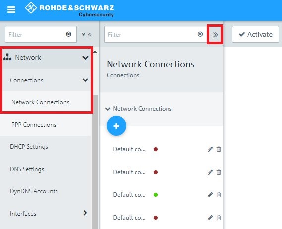
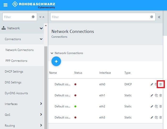
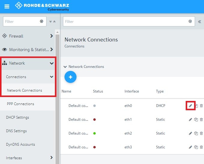
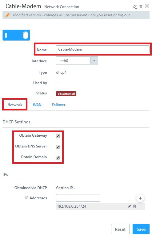
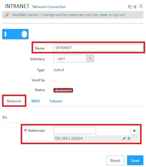
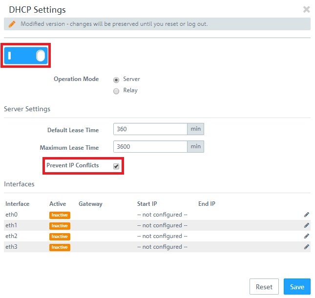
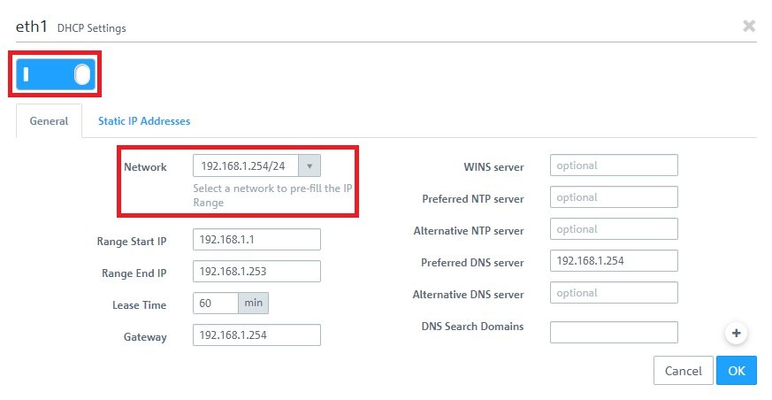
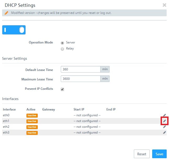
Image Added

2.3.4) Activate DHCP address assignment by clicking the switch and, from the drop-down menu Network, select the IP network associated with interface eth1. The remaining parameters are entered automatically.
Info:
  • If required, you can adjust parameters such as the DHCP address range or the DNS servers.
Image Removed

Image Added


2.4) Creating the desktop objects:

2.4.1) Click the button to Create an Internet object.
Image Removed

Image Added

2.4.2) Modify the following parameters:
  • Object Name: Enter a descriptive name.
  • Connections: In the drop-down menu, select the WAN object created in steps 1.1.4 - 1.1.5 (static IP address assignment), 1.2.2 (dynamic address assignment by DHCP) or 1.3.5 (PPPoE connection) and click on the “+” icon to add the object.
Image Removed

Image Added

2.4.3) Click the button to create a network.
Image Removed

Image Added

2.4.4) Modify the following parameters:
  • Name: Enter a descriptive name.
  • Interface: From the drop-down menu, select the interface eth1.
  • Network IP: Click in the input field to automatically enter the network assigned to interface eth1.
Image Removed

Image Added


2.5) Allow communication from the local network to the Internet:

2.5.1) On the desktop, click the network object and select the Connection Tool. Link the network object to the Internet object. .
Image Removed

Image Added

2.5.2) For the outgoing communications, add the necessary protocols by means of the “+” icon.
Image Removed

Image Added


2.6) Saving and activating the configuration steps:

2.6.1) Click on the Activate button to accept and enable the changes.
Image Removed

Image Added


2.7) Further steps Configuring the UTM features:

The configuration of the UTM functions is described in the following articles:
  • LANCOM R&S®Unified Firewall: Configuring the HTTP(S) proxy to use UTM functions
DokumentlinksymbolImage Removed
  • LANCOM R&S®Unified Firewall: Configuring the URL/Content Filter
Image Removed
  • LANCOM R&S®Unified Firewall: Configuring the Application Filter
DokumentlinksymbolImage Removed
  • DokumentlinksymbolImage Added
  • LANCOM R&S®Unified Firewall: Configuring the URL/Content Filter
DokumentlinksymbolImage Removed