This document describes the steps to configure the packet filter in a LANCOM R&S®Unified Firewall.
This basic functionality is required to make use of the UTM functions (e.g.
application filter, the
URL/content filter,
antivirus, etc.) of the Unified Firewall.
Requirements:
- A configured and functional Internet connection on the Unified Firewall
- Any web browser for access to the web interface of the Unified Firewall
1) Procedure:In this example configuration, the services (e.g. HTTP, HTTPS, FTP, etc.) used from the local network to the Internet should be regulated by the Unified Firewall.
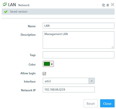
For this purpose, the configuration of the Unified Firewall already features
a desktop object of the type Network, which specifies the physical firewall interface that is connected to the local network. Also, the IP address range of the local network is entered in
CIDR notation.
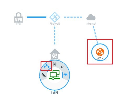
1.1) In the
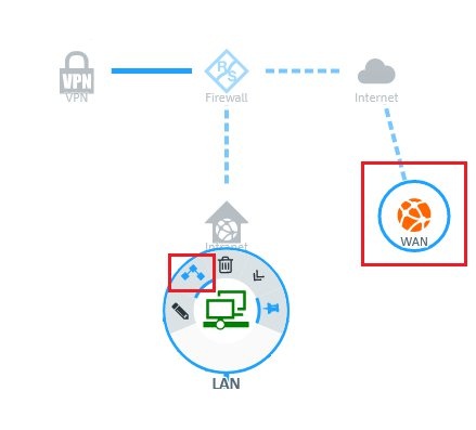
LAN network object, click the
“Connection” icon and then click the Internet object that was created for the existing
WAN connection.
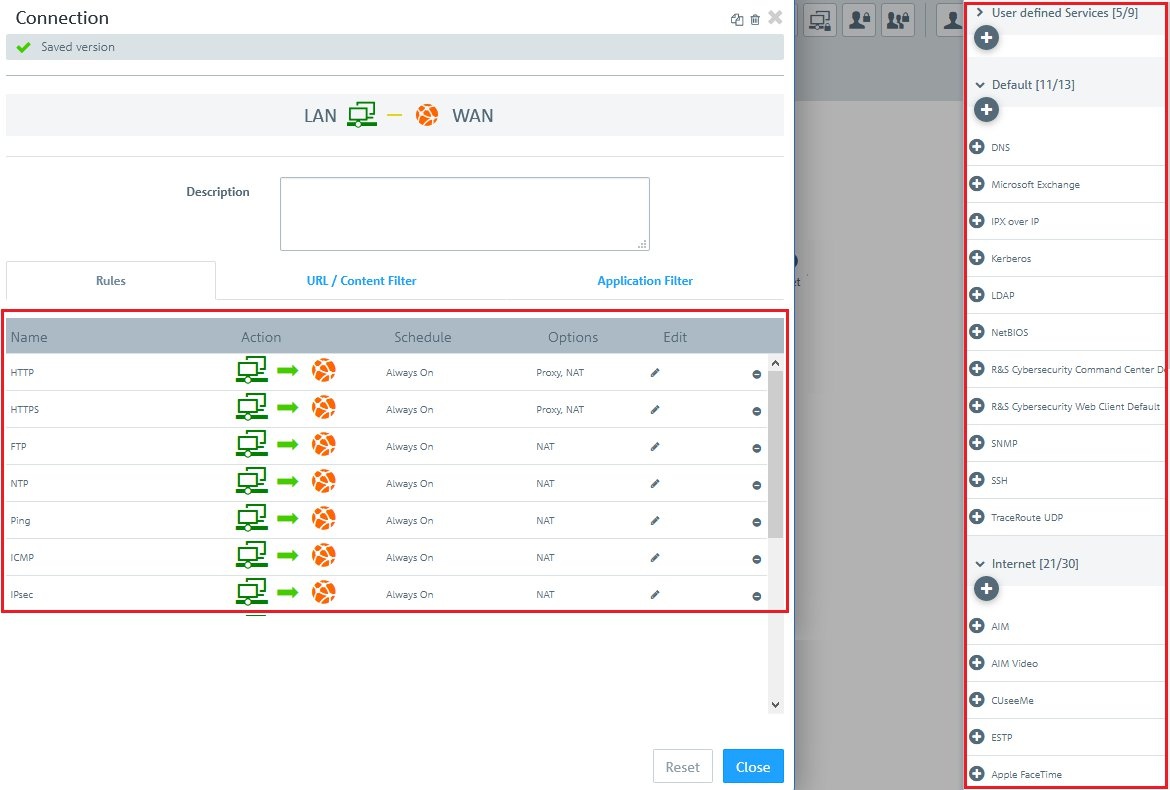
1.2) Assign the desired services and protocols to the
LAN network object by means of the “+” icon.
Note:A Unified Firewall uses a deny-all strategy. You therefore have to explicitly allow communication.
If you are adding services only,
you have already achieved the basic functionality of the packet filter.
In section 2 of this document we discuss further options for configuring the individual services.
1.3) Click on
Save to
accept these basic packet-filter functions.
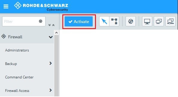
1.4) Implement the configuration changes in the Unified Firewall by clicking
Activate.
 2) Advanced settings for the services:
2.1) You can
configure the advanced settings of the rules for the services in a (network) object by clicking the “
Connection” icon and then clicking the
Internet object that was created for the existing WAN connection.
2.2) On the
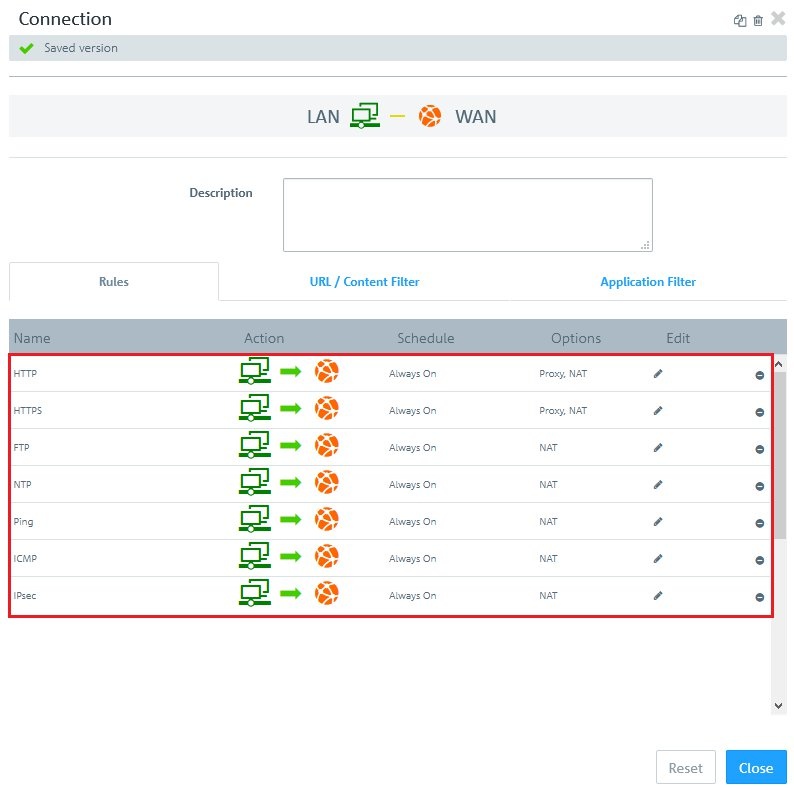
“Rules” tab you can make
direct changes to the rules in the columns Action, Schedule, and Options by clicking on the link for the corresponding function.
- In the Action column, each click immediately activates a different action (off, bi-directional, left to right, or right to left).
The relevant communication direction is visible in the header area of this dialog (e.g. LAN – WAN). In this example (see figure), communication takes place from the LAN (left) to the WAN (right). As the option NAT has been assigned, the WAN IP address becomes the source. - Clicking on a link in the Schedule column opens the dialog for configuring this function.
- Use the sliders to set specific times and days of the week.
- Clicking “Always on” activates the rule permanently.
- Clicking “Always off” disables the rule permanently.
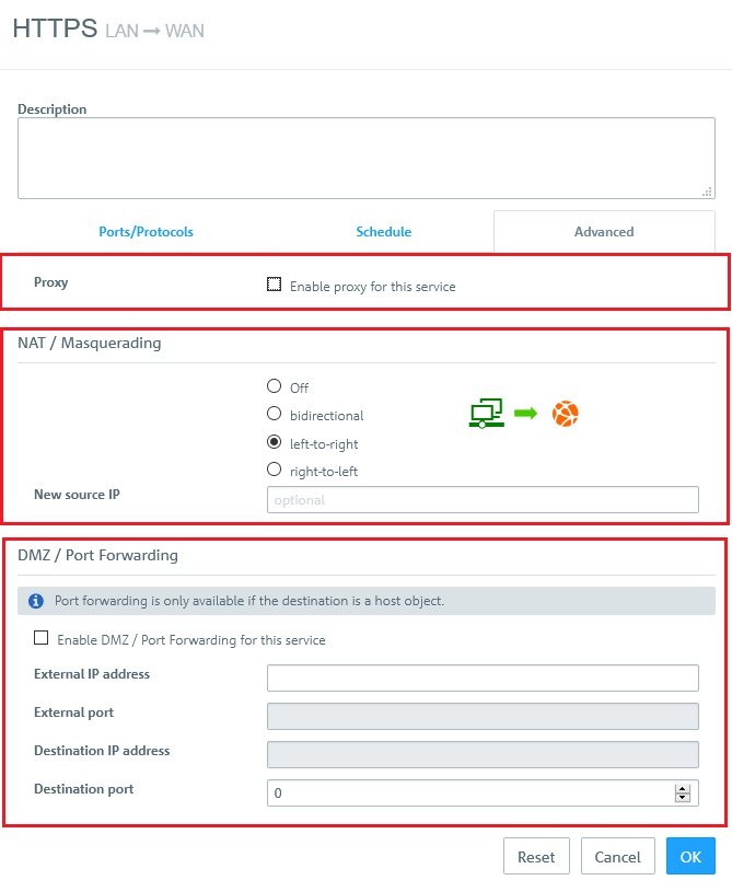
- If you click on a link in the Options column, a dialog opens with the advanced settings. The Advanced tab contains the following options:
- Proxy:
For predefined firewall rules with predefined services, only if the predefined services allow a proxy (HTTP, HTTPS, FTP, SMTP, SMTPS, POP3 or POP3S). Set a checkmark in this box to enable the proxy for this rule.
For firewall rules with customized services only: Select a proxy for this rule from the drop-down list. To remove the proxy, click on the right-hand side of the selected proxy.
- NAT / Masquerading:
Specify the desired direction for NAT/masquerading (bi-directional, left-to-right, or right-to-left), or disable the function for that rule (Off) by selecting the appropriate radio button. The default setting depends on the source and destination objects selected for the connection.
- New source IP:
Optional: If you have multiple outgoing IP addresses, specify the IP address to use for the source NAT. If no IP address is specified, the system automatically selects the main IP address of the outgoing interface.
- DMZ / Port Forwarding:
If a single host object is the destination of the firewall rule, you can set a checkmark in this box to enable DMZ and port forwarding for this rule.
- External IP address:
Optional: Enter the destination IP address of the data being processed. The DMZ rule is applied to this traffic only. This IP address has to be one of the IP addresses of the firewall.
- External port:
Displays the original destination port of the traffic being processed depending on the port specified on the “Ports/Protocols” tab.
- Destination IP address:
Displays the new destination IP address for the traffic (after processing).
- Destination port:
Optional: Specify the destination port of the traffic (after processing).
 Note:
Note:- Clicking in the Edit column on the edit icon allows you to make all of the settings for the service in an overall dialog.
- Clicking on the Delete icon removes the service from the list.