Description: This document describes the configuration steps required on a LANCOM managed switch of the GS-23xx series in order to configure a Voice VLAN. If an LLDP-MED compatible VoIP telephone is connected to the switch, the switch recognizes the telephone and activates the Voice VLAN on the switch port. As the Voice VLAN is tagged on this port (tagging mode Hybrid), tagging has to be also activated on the VoIP telephone. It is also possible to connect additional network devices to this port, which are to communicate in another VLAN. For this purpose there is a separate port on many VoIP telephones a PC can be connected to for example. This can save an additional switch.
Requirements: - LANCOM switch of the GS-23xx series with current SwitchOS firmware (download latest version)
- IP telephone supporting LLDP-MED
- Any web browser for accessing the webinterface
- The VoIP telephone has to be configured to tag packets with the Voice VLAN ID (active tagging)
Scenario:- In this example, the Voice VLAN has the ID 200, and LLDP is to be used as the discovery protocol.
- The IP telephone should be assigned this VLAN ID automatically as soon as it is connected to the designated switch port.

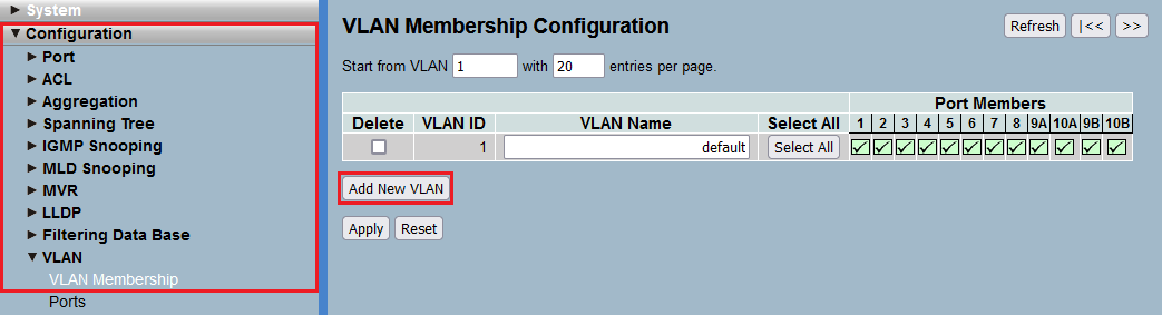
Procedure: 1) Connect to the switch via the webinterface, go to the menu Configuration → VLAN → VLAN Membership and click Add New VLAN. 2) Modify the following parameters and click Apply: - VLAN ID: Enter the VLAN ID of the Voice VLAN (in this example the VLAN ID 200).
- VLAN Name: Enter a descriptive name for the Voice VLAN (in this example Voice).
- Port Members: Select the Port, the router is connected to (in this example Port 8).

3) Connect the IP telephone to the switch. For this example we use switch port 1.
4) Go to the menu Configuration → LLDP → LLDP Configuration and set the Mode to Enabled for the ports, where a VoIP telephone is connected, to activate LLDP (in this example Port 1). Click Apply afterwards. die Ports, an denen ein VoIP-Telefon angeschlossen ist, auf Enabled, um LLDP auf diesem Port zu aktivieren (in diesem Beispiel für den Port 1). Klicken Sie anschließend auf Apply.  5. Wechseln Sie in das Menü Configuration → LLDP → LLDP-MED-Configuration. 
6. Klicken Sie bei Policies auf die Schaltfläche Add new policy.

7. Passen Sie in der Policy die folgenden Parameter an und klicken auf Apply: - Application Type: Wählen Sie im Dropdown-Menü die Option Voice aus.
- Tag: Wählen Sie im Dropdown-Menü die Option Tagged aus.
- VLAN ID:Tragen Sie die VLAN-ID des Voice-VLANs ein (in diesem Beispiel die VLAN-ID 200).
- L2 Priority: Tragen Sie den Wert 6 ein.
- DSCP: Tragen Sie den Wert 49 ein.

8. Aktivieren Sie bei Policy Port Configuration für den Port, an dem das VoIP-Telefon angeschlossen ist (in diesem Beispiel der Port 1) die in Schritt 6. erstellte Policy und klicken auf Apply. 
5) Configure LLDP-MED on port 1 with the following values: - Application type: Voice
- VLAN ID: 200
- L2 priority: 6
- DSCP: 49
5) Recheck the LLDP-MED Neighbor information after the LLDP negotiation between the switch and the IP telephone. 6) Switch to the menu Voice LAN → Configuration. - Enable the Voice LAN feature and set the VLAN ID to 200.
- Set the port mode of switch port 1 to Auto and set the Discovery Protocol to LLDP.
7) Make sure that port 1 is a member of the VLAN with the ID 200. 8) This concludes the configuration. Save the configuration changes to the switch. 9) Enter the VLAN ID (here the 200) in the configuration of your telephone.
Function check: To check the functionality please connect a PC to the switch, e.g. to port 3 and perform the following configuration on the switch: - Port 3 must be a member of the VLAN with the ID 200.
 - In the VLAN port configuration, port 3 needs to be set with the PVID 200.
 - Save the configuration to the switch. You should now be able to send a ping from the PC connected to port 3 to the IP telephone connected to port 1.
|
|