Description:
In many scenarios a redundant connection of network devices is required, which can only be implemented by redundant cabling. In order to prevent a loop, which would cripple the whole network, the Spanning Tree Protocol (STP) was created. By using STP only the shortest path is set active and the communication is transmitted via this path. When an outage of the active path occurs, a change to another path takes place.
This article describes how Rapid Spanning Tree Protocol (RSTP) can be configured on a GS-3xxx series switch.
In contrast to STP topology changes happen much faster with RSTP, thus minimizing downtimes.
Please also note the article Best Practice recommendations for redundant scenarios with LANCOM switches.
The features Loop Protection and Spanning Tree should not be used together on the same port, as both features can deactivate ports. Otherwise this could lead to network problems!
Requirements:
- LCOS SX as of version 4.00 Rel (download latest version)
- At least one other network device with active RSTP besides the GS-3xxx series switch
- Any web browser for accessing the webinterface
Procedure:
1) Configuring RSTP on the switch:
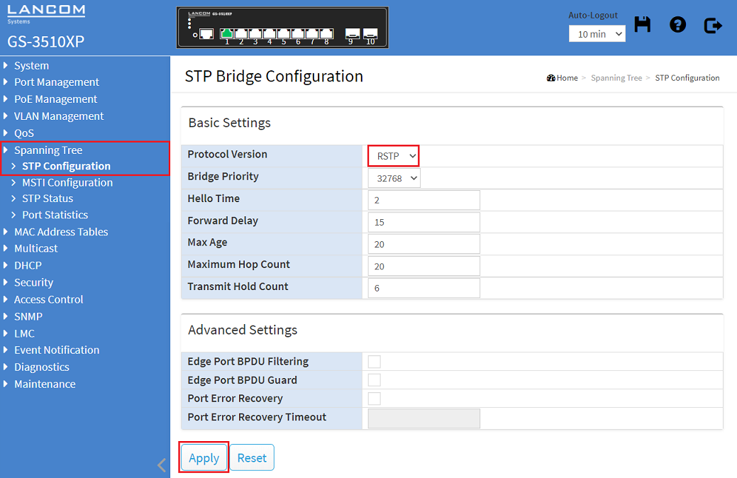
1.1) Connect to the webinterface of the device, go to the menu Spanning Tree → STP Configuration and for the Protocol Version select the option RSTP. Click Apply afterwards.
Optionally you can modify the Bridge Priority. The lower the value, the higher the priority. The device with the lowest Bridge Priority becomes the Root-Bridge. If two devices have the same Bridge Priority, the device with the lower MAC address becomes the Root-Bridge.
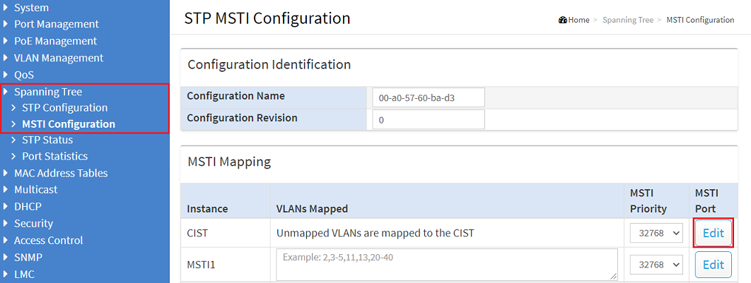
1.2) Go to the menu Spanning Tree → MSTI Configuration and under MSTI Mapping click on Edit for the Instance CIST under MSTI Port.
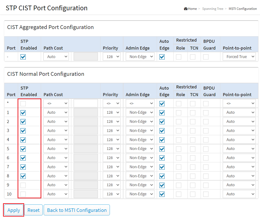
1.3) Under CIST Normal Port Configuration select all ports where RSTP is to be used and click Apply afterwards.
If you are using Link Aggregation (e.g. LACP ), under CIST Aggregated Port Configuration the option STP Enabled must be active (default setting).
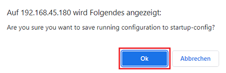
1.4) Click on the red disk symbol In the upper right corner to save the configuration as the start configuration.
The start configuration is retained even if the device is restarted or there is a power failure.

1.5) Acknowledge the save process by clicking OK .
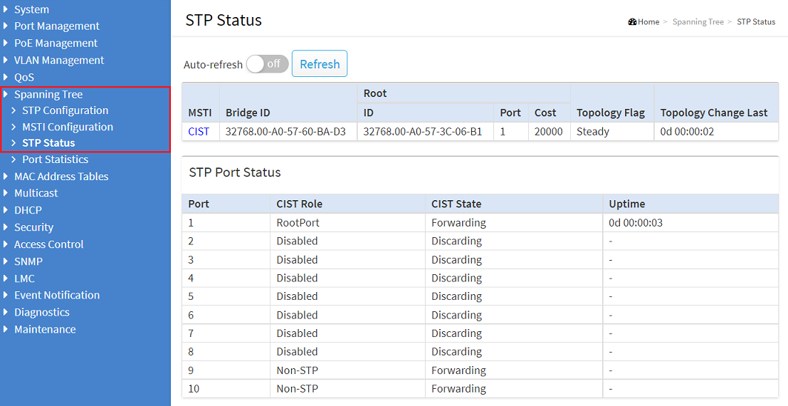
2) Viewing the Spanning Tree status for individual switch ports:
The status information for individual switch ports can be viewed in the menu Spanning Tree → STP Status.