
Description:
In highly heterogeneous environments with network devices from different manufacturers, integrating a LANCOM R&S®Unified Firewall with UTM features can be a challenge. The simplest solution is to use the transparent bridge mode. This allows all of the features of existing network devices to remain in use (e.g. existing VPN connections).
This article describes how the UTM features of a LANCOM R&S®Unified Firewall are operated in heterogeneous network environments by means of the transparent bridge mode.
All UTM functions can be operated in this scenario.
Requirements:
- LANCOM R&S®Unified Firewall with LCOS FX as of version 10.13 RU8
- Basic or full license (full license required for UTM functions)
- Installed and functional network scenario
- The Unified Firewall must be in its ex-factory state
- Web browser for configuring the Unified Firewall.
The following browsers are supported:- Google Chrome
- Chromium
- Mozilla Firefox
Scenario:
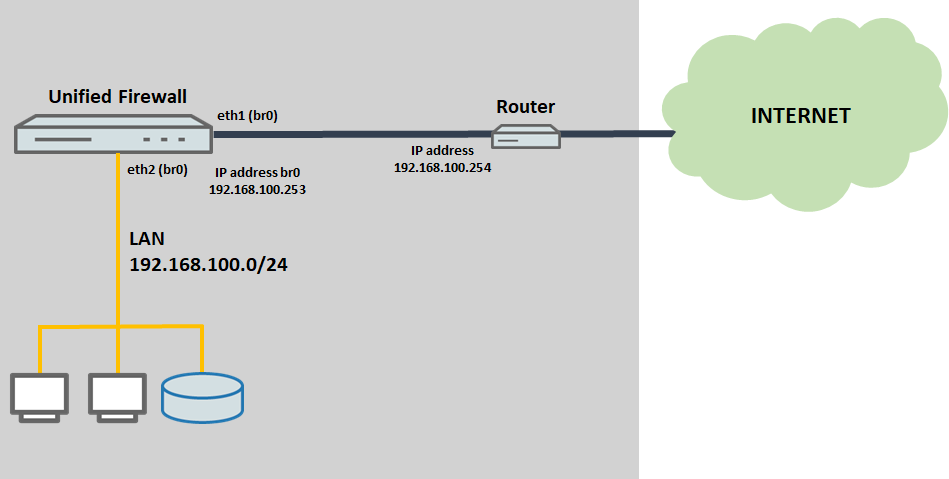
- The router supports the IP network 192.168.100.0/24 and operates with the IP address 192.168.100.254.
- The router works as the default gateway and also operates the DHCP and DNS servers.
- On the Unified Firewall, the interfaces eth1 and eth2 are collected in bridge br0 and this is assigned the IP address 192.168.100.253.
Procedure:
1) Configuring transparent bridge mode on the Unified Firewall:
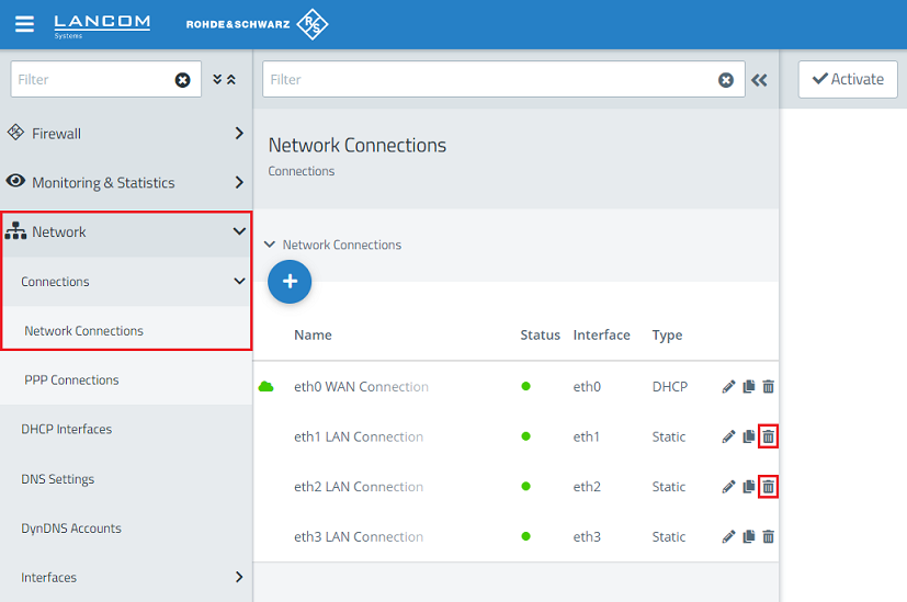
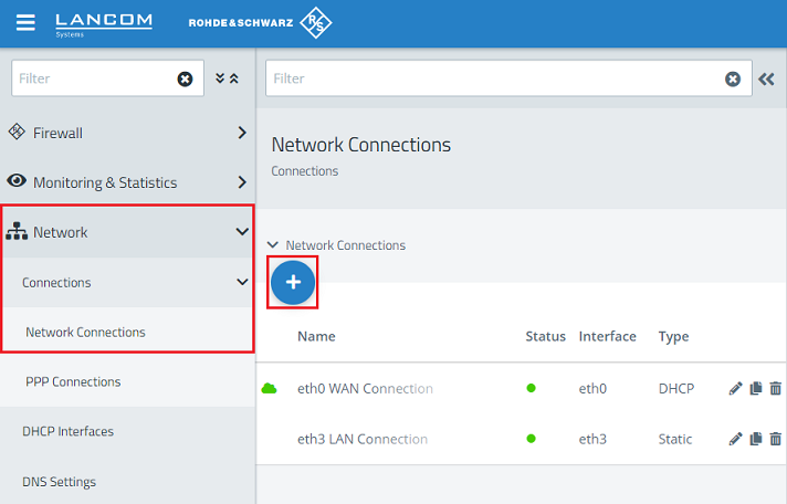
1.1) Connect to the Unified Firewall using a web browser, switch to the menu Network → Connections → Network Connections, and use the “trash can” icons to delete two unused connections so that the two Ethernet ports are available for the bridge (in this example the interfaces eth1 and eth2).
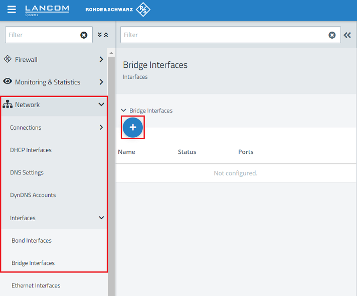
1.2) Navigate to the menu Network → Interfaces → Bridge Interfaces and click on the “+” icon to create a new interface.
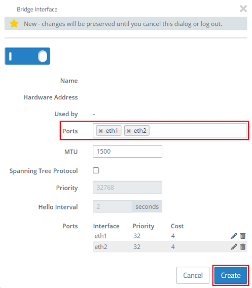
1.3) Enter the ports deleted in step 1.1 (in this example eth1 and eth2) and click Create.
1.4) Change to the menu Network → Connections → Network Connections and click on the “+” icon to create a new interface.
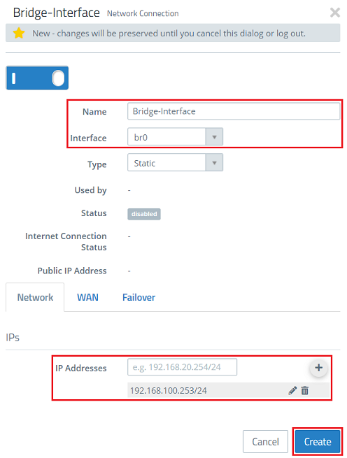
1.5) Modify the following parameters and then click Create:
- Name: Enter a descriptive name (in this example Bridge-Interface).
- Interface: Select the bridge interface created in step 1.3 (in this case br0).
- IP Addresses: Enter a free IP address in CIDR format on the network where the Unified Firewall is to be integrated (in this example 192.168.100.253/24).
On the WAN tab, do not set a default gateway!
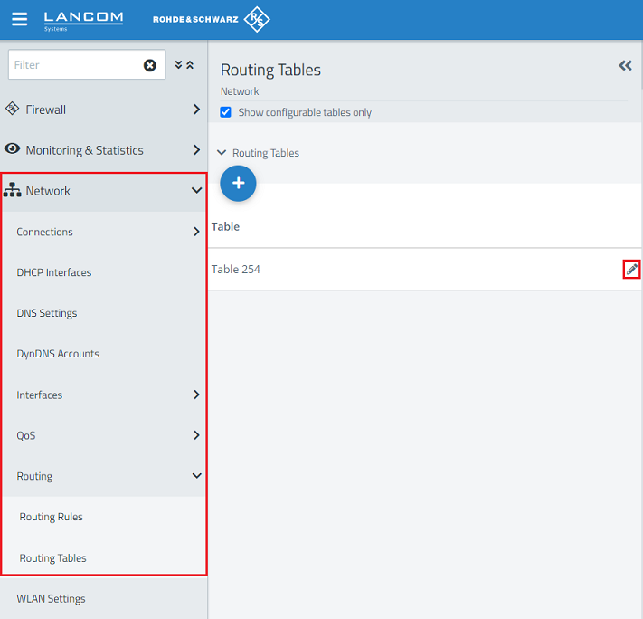
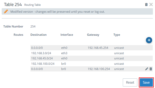
1.6) Change to the menu Network → Routing → Routing Tables and click on the “edit” icon to modify the settings of the Table 254.
1.7) Click on the “+” icon to create an additional routing entry.
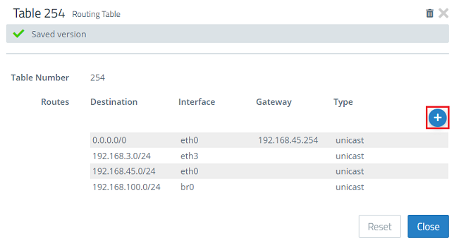
1.8) Modify the following parameters and then click OK:
- Interface: From the drop-down menu select the bridge interface created in step 1.3 (in this case br0).
- Destination: Enter the address 0.0.0.0/0. This routes packets for any destination via this route (default route).
- Gateway: Enter the IP address of the default gateway on the available network.
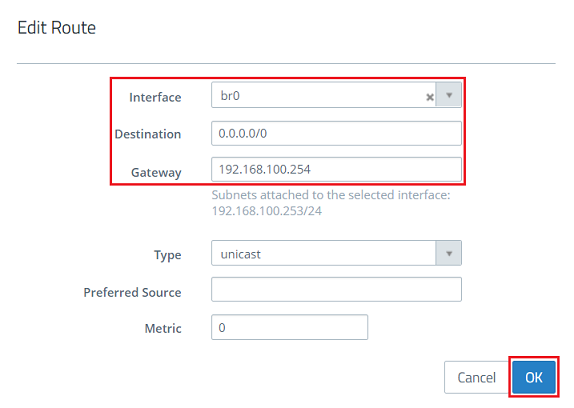
1.9.) Click on Save.
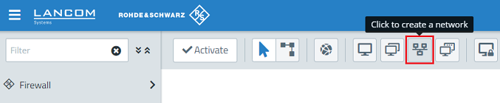
1.10) Click the icon to create a new network to create an object for the local network.
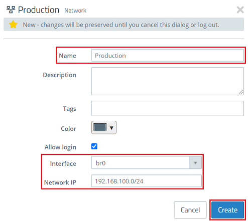
1.11) Modify the following parameters and then click Create:
- Name: Enter a descriptive name (in this example Production).
- Interface: Select the bridge interface created in step 1.3 (in this case br0).
- Network IP: Enter the network address of the existing network in CIDR format (in this example 192.168.100.0/24).
1.12) Click the icon to create a new network once again to create an object for the Internet connection.
1.13) Modify the following parameters and then click Create:
- Name: Enter a descriptive name (in this example Internet).
- Interface: Select the interface any.
- Network IP: Enter the address 0.0.0.0/0. This stands for any destination.

2) Allow DHCP communication:
A firewall rule is required to enable DHCP communication between the end devices and the DHCP server on the router.
If a DHCP server is operated “behind” the Unified Firewall, the DHCP packets do not pass through it. In this case, the following configuration steps are not necessary.
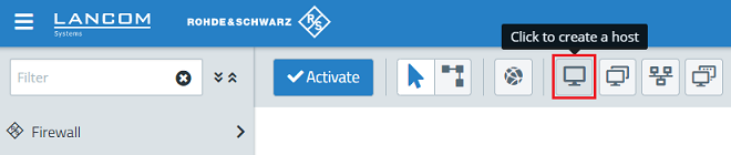
2.1) Click the icon to create a host to create an object for the DHCP source.
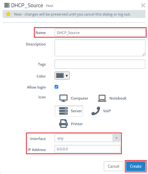
2.2) Modify the following parameters and then click Create:
- Name: Enter a descriptive name (in this example DHCP_Source).
- Interface: Select the interface any.
- IP address: Enter the IP address 0.0.0.0. All DHCP requests are performed with this source address.
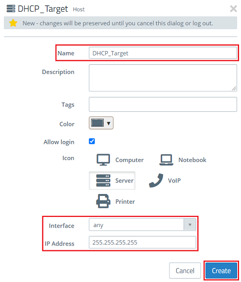
2.3) Click the icon to create a host once again to create an object for the DHCP target.
2.4) Modify the following parameters and then click Create:
- Name: Enter a descriptive name (in this example DHCP_Target).
- Interface: Select the interface any.
- IP address: Enter the IP address 255.255.255.255. All DHCP requests are performed with this target address. This is the broadcast address.
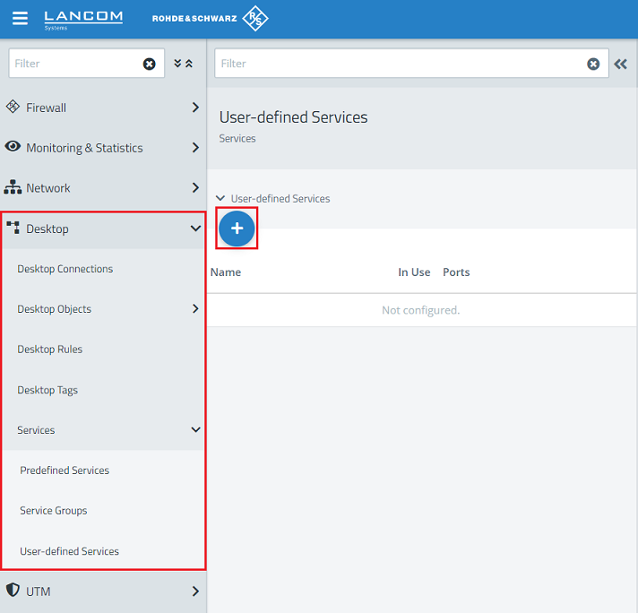
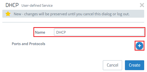
2.5) Change to the menu Desktop → Services → User-defined Services and click on the “+” icon to create a user-defined service.
2.6) Give it a descriptive name and click on the “+” icon to add the Ports and Protocols.
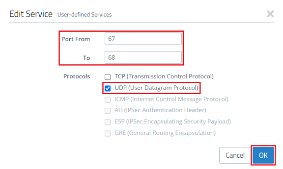
2.7) Enter the ports 67 to 68 and select the UDP protocol. Then click on OK.
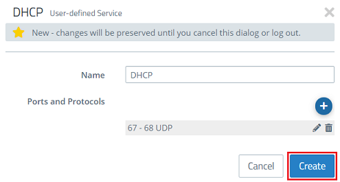
2.8) Click on Create.
2.9) On the desktop, click the DHCP source object (DHCP_Source) created in step 2.2, select the connection tool and click the DHCP target object (DHCP_Target) created in step 2.4.
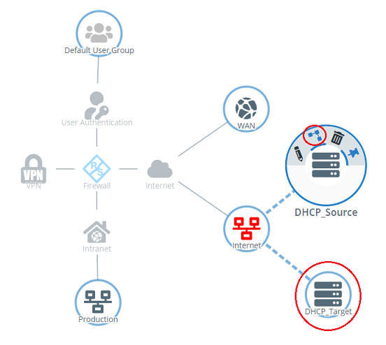
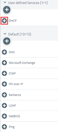
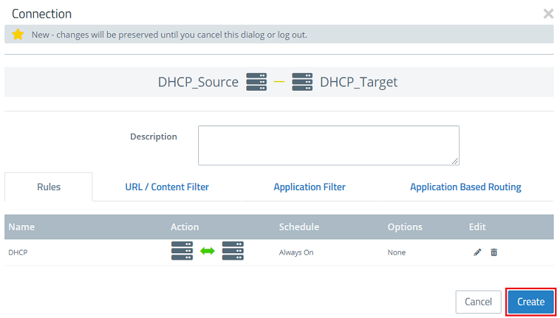
2.10) Use the “+” icon to add the user-defined service created for DHCP in step 2.6 - 2.8.
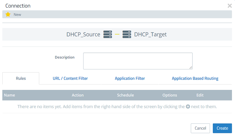
2.11) Click Create to create the firewall rule.
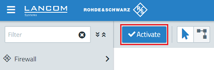
2.12) This concludes the configuration of the transparent bridge. Finally, implement the changes by clicking Activate.
3) Configuring UTM features:
You can now set up the UTM features:
- LANCOM R&S®Unified Firewall: Configuring the HTTP(S) proxy to use UTM functions
- LANCOM R&S®Unified Firewall: Configuring the mail proxy in order to use e-mail security features
- LANCOM R&S®Unified Firewall: Configuring the packet filter
- LANCOM R&S®Unified Firewall: Configuring the Application Filter
- LANCOM R&S®Unified Firewall: Configuring the antivirus feature (up to and including LCOS FX 10.13)
- LANCOM R&S®Unified Firewall: Configuring the URL/Content Filter