
Description:
Some scenarios require Wi-Fi traffic from branch offices to be directed via the central site. Operating a WLAN Controller allows this to be achieved with a WLC-Tunnel. Without a WLAN Controller, it is possible to transmit the Wi-Fi data traffic to a LANCOM router via an L2TP tunnel, and break-out the data there.
This article describes how to set up an L2TPv3 connection between a LANCOM access point with LCOS LX and a LANCOM router. As a consequence, all Wi-Fi data traffic is transmitted via the L2TP tunnel to the router, and it breaks-out there.
Requirements:
- LCOS as of version 10.80 (download latest version)
- LCOS LX as of version 6.12 (download latest version)
- LANtools as of version 10.80 Rel (download latest version)
- Previously configured and functional Wi-Fi on the access points
- Existing and functional Internet connection to the router at the central site
- The access points must be able to reach the router at the central site (e.g. via VPN)
Scenario:
All traffic from the SSID L2TP-SSID should be routed from the access points in the branch offices through the L2TP tunnel to the router at the central site, and it breaks-out there.
Router at the central site:
- The router is configured with the network INTRANET with the IP address range 172.16.0.0/24 and the IP address 172.16.0.254.
- An L2TPv3 tunnel has to be created on the router to transmit the Wi-Fi traffic.
- An additional network must be created for the Wi-Fi traffic. This is assigned the name L2TP-Network with the IP address range 192.168.1.0/24 and the IP address 192.168.1.254.
- The router acts as a gateway in this network.
- The DHCP server is activated for this network, so that Wi-Fi end devices can obtain an IP address.
Access points at the branch offices:
- An L2TPv3 tunnel has to be created on the access point to transmit the Wi-Fi traffic.
Procedure:
1) Configuring the L2TPv3 connection on the LANCOM router:
Just one L2TP endpoint must be configured on the router. This is where all of the access points can log-on.
We recommend that you create a separate L2TP Ethernet entry for each SSID that is to be transmitted via L2TP. This allows a separate network to be created for each SSID.
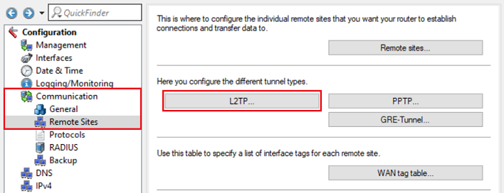
1.1) Open the configuration for the router in LANconfig and switch to the menu item Communication → Remote Sites → L2TP.
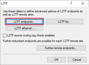
1.2) Go to the menu L2TP endpoints.
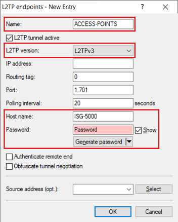
1.3) Create a new L2TP end point and adjust the following parameters:
- Name: Enter a descriptive name for the L2TP endpoint (in this example ACCESS-POINTS).
- L2TP version: From the drop-down menu, select the option L2TPv3. This is necessary because access points with LCOS LX only support L2TPv3.
- Host name: Enter a name for the router (in this example ISG-5000).
- Password: Enter a password, which the access points use for authentication.
Leave the field IP address empty so that all access points can communicate via the same L2TP endpoint. This L2TP endpoint therefore acts as a wildcard.
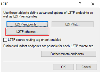
1.4) Go to the menu L2TP Ethernet.
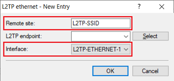
1.5) Create a new entry and adjust the following parameters:
- Remote site: Enter a descriptive name for the Wi-Fi SSID from which the data traffic is to be transmitted over the L2TP tunnel (in this example L2TP-SSID). This must also be assigned as the Remote site in step 2.4 on the access point.
- Interface: Select a previously unused L2TP interface. For this example we are using the interface L2TP-ETHERNET-1.
Leave the field L2TP endpoint empty so that the router accepts any sessions.
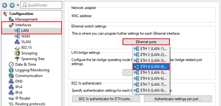
1.6) Go to the menu Interfaces → LAN → Ethernet ports and assign a LAN interface that is not yet used to the Ethernet port used to connect the L2TP network (in this example the port ETH 4 is already assigned to the logical interface LAN-4).
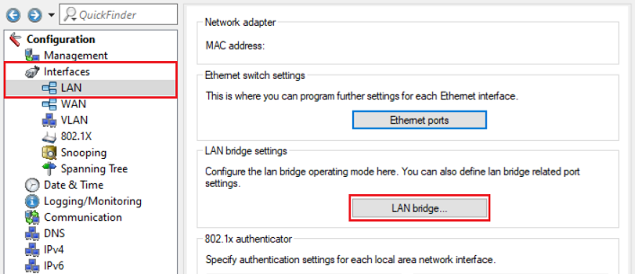
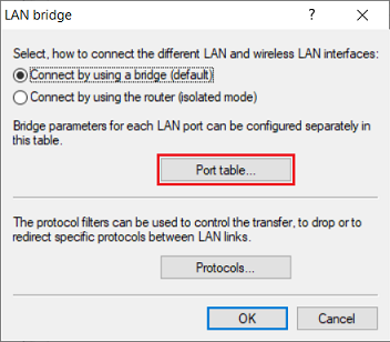
1.7) Go to the menu LAN bridge.
1.8) Make sure that the option Connect by using a bridge (default) is selected.
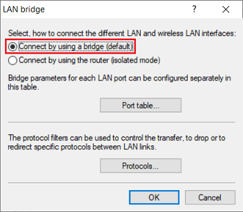
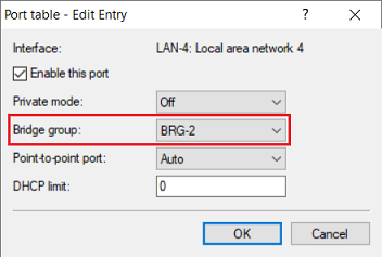
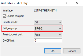
1.9) Go to the Port table menu.
1.10) Assign a bridge group that is not yet used to the logical LAN interface selected in step 1.6 and to the L2TP interface selected in step 1.5 (in this example BRG-2).
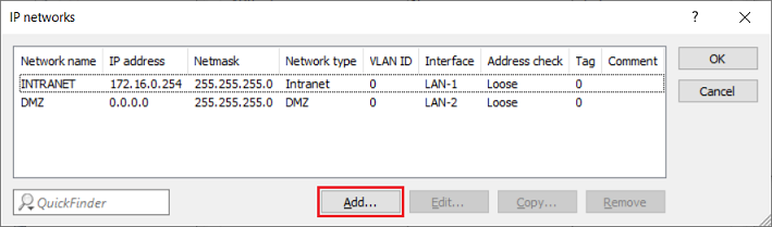
1.11) Switch to the menu IPv4 → General → IP networks.
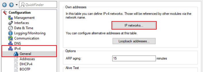
1.12) Click Add to create a network for the L2TP data traffic.
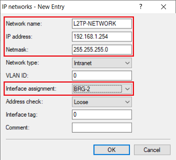
1.13) Change the following parameters:
- Network name: Enter a descriptive name for the L2TP network (in this example L2TP-NETWORK).
- IP address: Enter an IP address from an as yet unused IP network (in this example 192.168.1.254).
- Netmask: Enter the corresponding subnet mask.
- Interface assignment: From the drop-down menu, select the bridge group created in step 1.10 (in this case BRG-2).
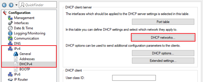
1.14) Switch to the menu IPv4 → DHCPv4 → DHCP networks.
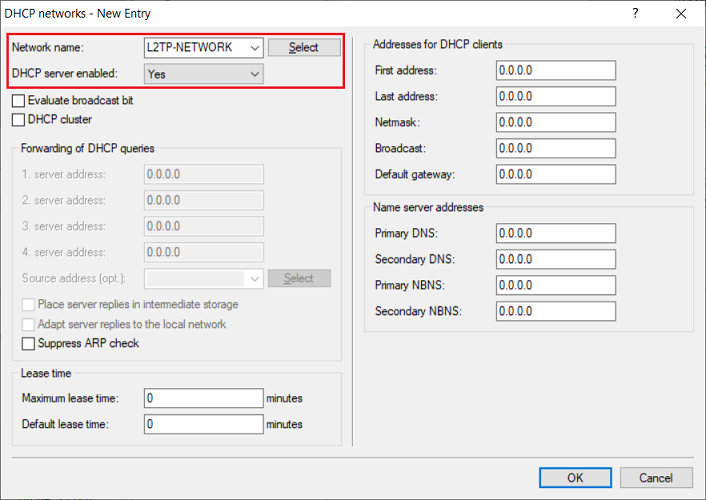
1.15) Create a new entry and adjust the following parameters:
- Network name: From the drop-down menu, select the L2TP network created in step 1.13.
- DHCP server enabled: From the drop-down menu, select the option Yes.
You can optionally restrict the available IP addresses using the fields First address and Last address and assign a separate DNS server.
1.16) This concludes the configuration of the L2TP connection on the LANCOM router. You can now write the configuration back to the device.
2) Configuring the L2TPv3 connection on the access point with LCOS LX:
We recommend that you create a separate L2TP Ethernet entry for each SSID that is to be transmitted via L2TP. This allows a separate network to be created for each SSID.
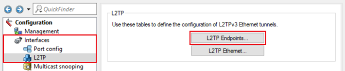
2.1) In the configuration of the access point, go to the menu Interfaces → L2TP → L2TP Endpoints.
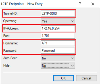
2.2) Create a new L2TP end point and adjust the following parameters:
- Tunnel-ID: Enter a descriptive name for the L2TP tunnel (in this example L2TP-SSID).
- IP-Address: Enter the IP address of the LANCOM router where it should be reached from the access point (in this example 172.16.0.254).
- Hostname: Enter a descriptive name for the access point (in this example AP1).
- Password: Enter the password used in step 1.3. This is used for authentication with the central router.
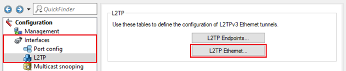
2.3) Go to the menu L2TP Ethernet.
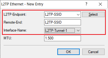
2.4) Create a new entry and adjust the following parameters:
- L2TP-Endpoint: From the drop-down menu, select the L2TP endpoint created in step 2.2 (in this case L2TP-SSID).
- Remote-End: Enter the Remote site of the LANCOM router set in step 1.5 (in this example L2TP-SSID).
- Interface-Name: Check that the interface is set to L2TP-Tunnel-1.
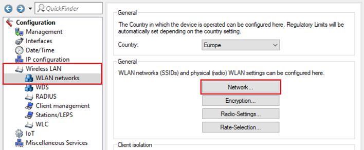
2.5) Go to the menu Wireless LAN → WLAN networks → Network.
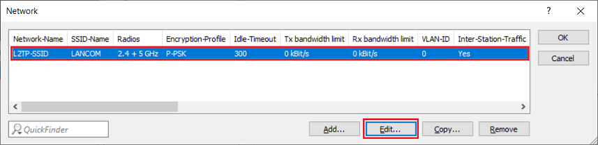
2.6) Select the SSID for which the data traffic is to be transmitted via the L2TPv3 tunnel and click Edit.
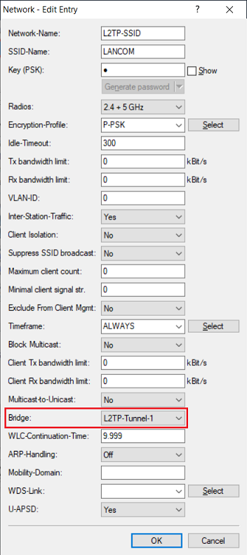
2.7) Under Bridge, select the L2TP interface that was set in step 2.4 (in this example L2TP-Tunnel-1).
2.8) This concludes the configuration of the access point. You can now write the configuration back to the device.