Description:
This article describes how a WireGuard connection can be set up between two LANCOM R&S®Unified Firewalls.
Connection monitoring is not implemented in WireGuard. Therefore a connection is always shown as active after the connection setup, even if the connection setup hasn't been completed.
Requirements:
- Two LANCOM R&S®Unified Firewalls with LCOS FX 10.12 or later
- A configured and functional Internet connection with local network on each Unified Firewall
- Web browser for configuring the Unified Firewall.
The following browsers are supported:- Google Chrome
- Chromium
- Mozilla Firefox
Procedure:
Configuring the WireGuard connections on the two Unified Firewalls must be carried out in parallel (steps 1.1 and 1.2 as well as 2.1 and 2.2), since the public key must be stored on the opposite Unified Firewall in each case. For the sake of clarity, however, the setup is described separately.
1) Configuring WireGuard on Firewall-1:
1.1) Configuring the WireGuard interface on Firewall-1:
A separate WireGuard interface has to be used for each WireGuard configuration (called WireGuard Connection). It is possible however, to enter several Peers in a configuration.
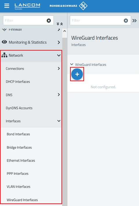
1.1.1) Connect to the web interface of Firewall-1 and navigate to the menu Network → WireGuard Interfaces. Click the “+” icon to create a new WireGuard interface.
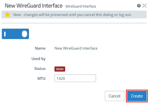
1.1.2) Click Create to generate the interface.
1.2) Configuring the WireGuard connection on Firewall-1:
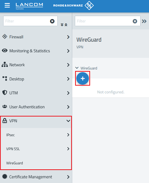
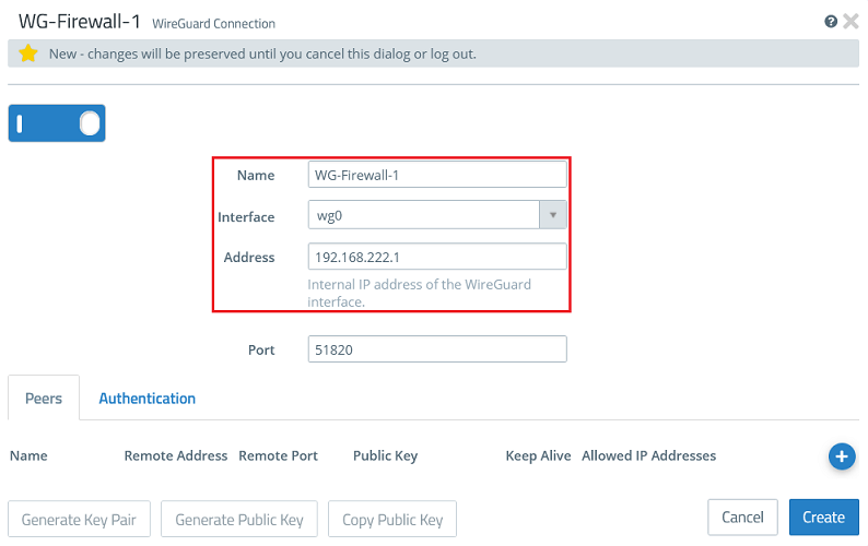
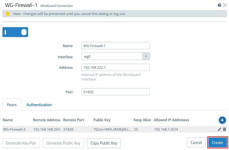
1.2.1) Go to the menu VPN → WireGuard and click the “+” icon to create a WireGuard connection.
1.2.2) Modify the following parameters:
- Name: Enter a descriptive name for the WireGuard connection (in this example WG-Firewall-1).
- Interface: From the drop-down menu, select the WireGuard interface created in step 1.1.
- Address: Enter an IP address from an as yet unused IP address range (in this example 192.168.222.1).
The port automatically increments when multiple WireGuard connections are created.
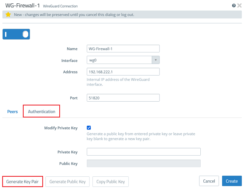
1.2.3) Go to the tab Authentication and click the button Generate Key Pair. This automatically generates the private key and the public key.
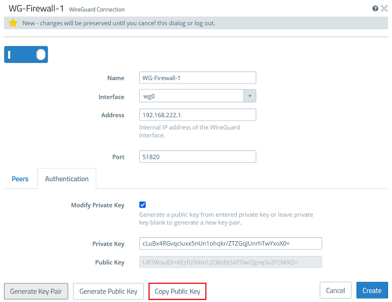
1.2.4) Click Copy Public Key and save it in a text file.
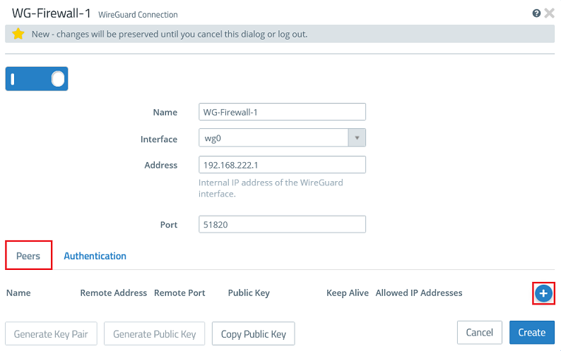
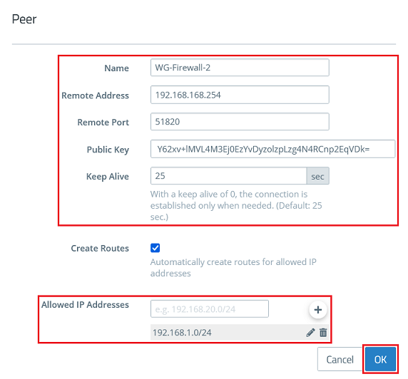
1.2.5) Go back to the tab Peers and click the “+” sign to specify the connection parameters for the remote site.
1.2.6) Modify the following parameters and click OK:
- Name: Enter a descriptive name for the connection to the remote site (in this example WG-Firewall-2).
- Remote Address: Enter the IP address where the remote site can be reached on the Internet (in this example an intermediate network is used and Firewall-2 has the IP address 192.168.168.254)
- Remote Port: Enter the port 51820. If you set a different port in step 1.2.4 or if this has been automatically set to a higher port when several WireGuard connections were created, you must enter this here accordingly.
- Public Key: Enter the public key for Firewall-2 copied in step 2.2.4.
- Keep Alive: Enter the value 25 so that Firewall-1 establishes the connection and the connection is maintained permanently (keep-alive value of 25 seconds).
- Allowed IP Addresses: Enter one or more IP networks at the remote site in CIDR notation (Classless Inter Domain Routing), which are to communicate with the local networks via the WireGuard connection (in this example 192.168.1.0/24).
It is possible to enter several Peers in a WireGuard configuration (they can be established at the same time). In doing so, multiple Unified Firewalls clients can be connected without needing to set up a new configuration for each Firewall. However it is practical set up a new WireGuard configuration, if the data traffic should be split (e.g. when different service providers should be connected).
1.2.7) Then click Create.
1.3) Allow data traffic between the local network and the WireGuard network:
Repeat the following steps for any other local or remote network that is to communicate via the WireGuard tunnel.
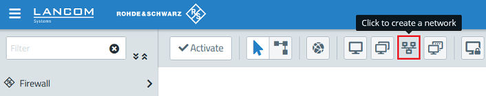
1.3.1) Click the icon to create a new network.
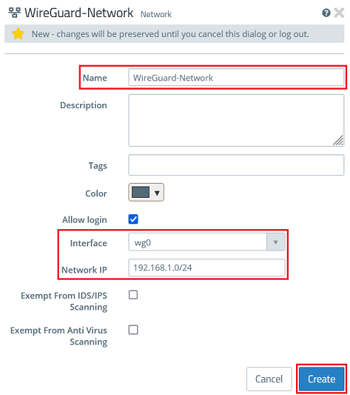
1.3.2) Modify the following parameters and then click Create:
- Name: Enter a descriptive name for the network (in this example WireGuard-Network).
- Interface: From the drop-down menu, select the WireGuard interface created in step 1.1.
- Network IP: Click in the box to display the network created under Allowed IP addresses in step 1.2.6, and select it (in this example 192.168.1.0/24). If several networks were created, they will all be displayed and you must select one of them.
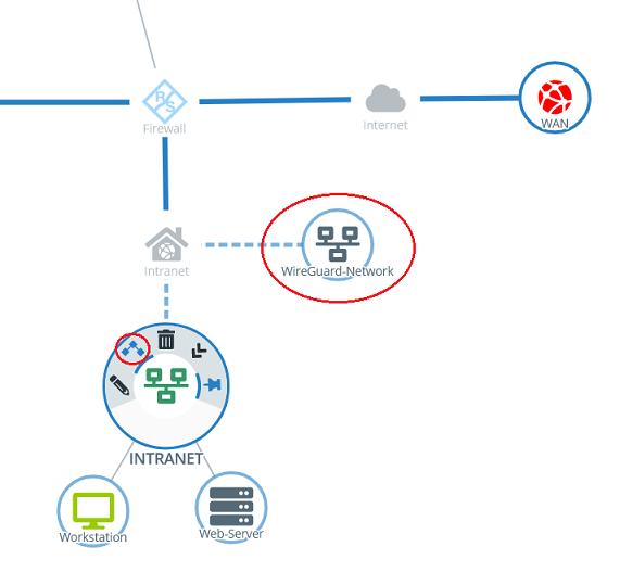
1.3.3) Click the object for the local network on the desktop (in this example INTRANET), select the connection tool, and click the object for the WireGuard network created in step 1.3.2.
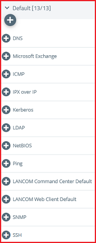
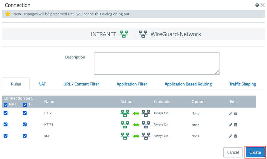
1.3.4) Add the protocols required for communication.
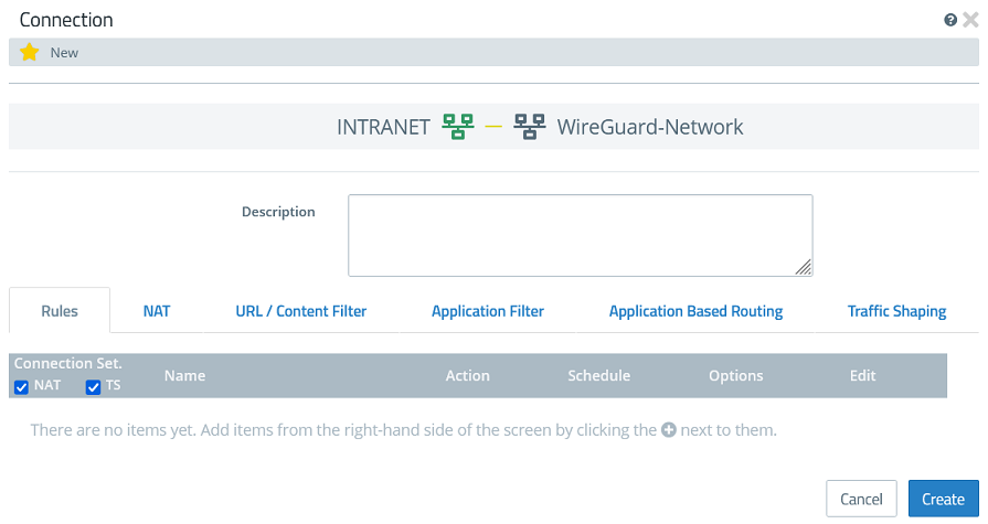
1.3.5) Click Create to generate the connection rules.
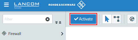
1.3.6) Finally, implement the changes by clicking Activate.
2) Configuring WireGuard on Firewall-2:
2.1) Configuring the WireGuard interface on Firewall-2:
2.1.1) Connect to the web interface of Firewall-2 and navigate to the menu Network → WireGuard Interfaces. Click the “+” icon to create a new WireGuard interface.
2.1.2) Click Create to create the interface.
2.2) Configuring the WireGuard connection on Firewall-2:
2.2.1) Go to the menu VPN → WireGuard and click the “+” icon to create a WireGuard connection.
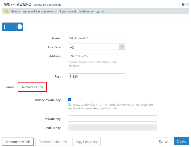
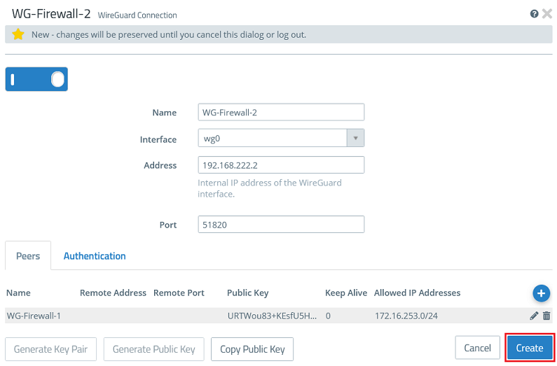
2.2.2) Modify the following parameters:
- Name: Enter a descriptive name for the WireGuard connection (in this example WG-Firewall-2).
- Interface: From the drop-down menu, select the WireGuard interface created in step 2.1.
- Address: Enter an IP address from the same IP address range used on the Firewall-1 in step 1.2.2 (in this example 192.168.222.2).
The port automatically increments when multiple WireGuard connections are created.

2.2.3) Go to the tab Authentication and click the button Generate Key Pair. This automatically generates the private key and the public key.
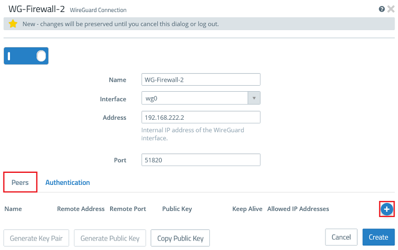
2.2.4) Click Copy Public Key and save it in a text file.

2.2.5) Go back to the tab Peers and click the “+” sign to specify the connection parameters for the remote site.
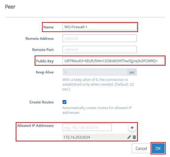
2.2.6) Modify the following parameters and click OK:
- Name: Enter a descriptive name for the connection to the remote site (in this example WG-Firewall-1).
- Public Key: Enter the public key for Firewall-1 copied in step 1.2.4.
- Allowed IP Addresses: Using CIDR notation, enter one or more IP networks at the remote site which are to communicate with the local networks via the WireGuard connection (in this example 172.16.253.0/24).
There is no need to specify the parameters Remote Address and Remote Port here, since Firewall-2 accepts the connection. Consequently, no value for Keep Alive can be specified either.
2.2.7) Then click Create.
2.3) Allow data traffic between the local network and the WireGuard network:
Repeat the following steps for any other local and/or remote network that is to communicate via the WireGuard tunnel.
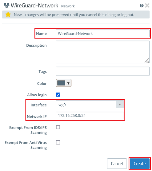
2.3.1) Click the icon to create a new network.
2.3.2) Modify the following parameters and then click Create:
- Name: Enter a descriptive name for the network (in this example WireGuard-Network).
- Interface: From the drop-down menu, select the WireGuard interface created in step 2.1.
- Network IP: Click in the box to display the network created under Allowed IP Addresses in step 2.2.6, and select it (in this example 172.23.253.0/24). If several networks were created, they will all be displayed and you must select one of them.
2.3.3) Click the object for the local network on the desktop (in this example INTRANET), select the connection tool, and click the object for the WireGuard network created in step 2.3.2.
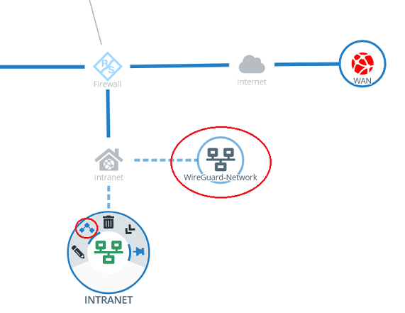
2.3.4) Add the protocols required for communication.
2.3.5) Click Create to generate the connection rules.
2.3.6) Finally, implement the changes by clicking Activate.
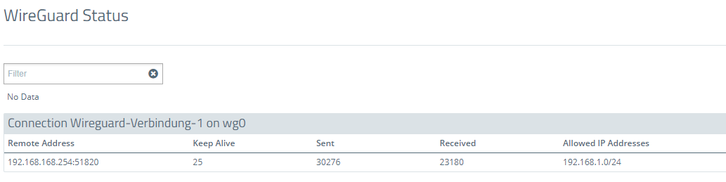
3) Viewing the status of the WireGuard connection:
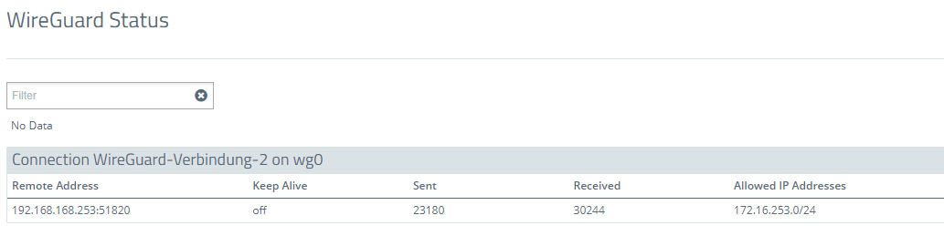
3.1) Navigate to the menu Monitoring & Statistics → WireGuard Status.
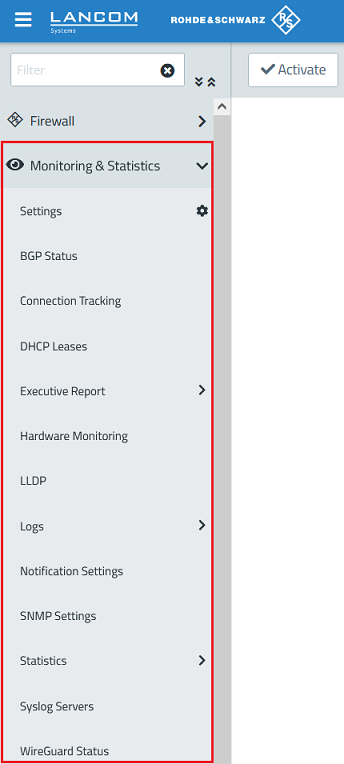
3.2) The WireGuard status menu displays, among other things, the IP address of the remote Unified Firewall, the number of sent and received packets, and the allowed networks:
- WireGuard status on Firewall-1:
- WireGuard status on Firewall-2: