Description:
This article describes how a WireGuard connection can be set up between a LANCOM R&S®Unified Firewall and the WireGuard client for Windows.
Connection monitoring is not implemented in WireGuard. As a result, a connection is always shown as active, even if it was not established at all.
The WireGuard standard currently does not support multiple WAN connections. Therefore it is not possible to select a specific WAN connection for a WireGuard connection. Due to this reason, no data can be transmitted via the WireGuard connection on a Unified Firewall with more than one Internet connection, as the Unified Firewall sends the response packets via another Internet connection than incoming packets.
Requirements:
- LANCOM R&S®Unified Firewallas of LCOS FX 10.12
- WireGuard Windows client
- A configured and functional Internet connection with local network on the Unified Firewall
- Web browser for configuring the Unified Firewall
The following browsers are supported:- Google Chrome
- Chromium
- Mozilla Firefox
Scenario:
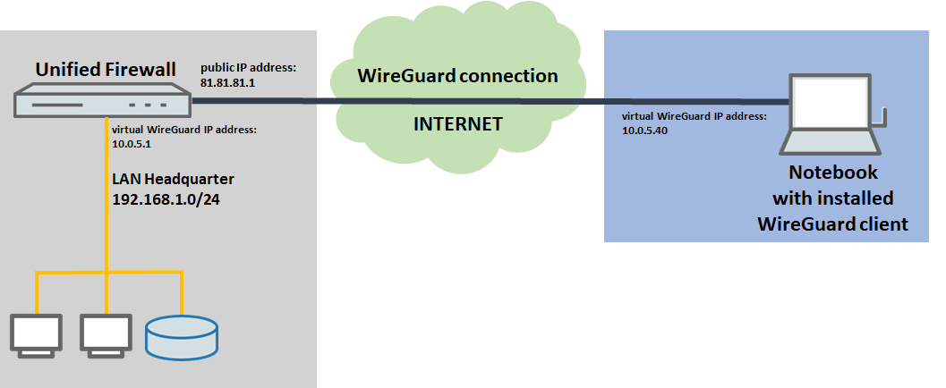
1) The Unified Firewall is connected directly to the Internet and has a public IPv4 address:
- A company wants its sales representatives to have access to the corporate network via a WireGuard client-to-site connection.
- The notebooks used by the sales representatives have the WireGuard client installed on them.
- The company headquarters has a Unified Firewall as a gateway with an Internet connection with the fixed public IP address 81.81.81.1.
- The local network at the headquarters has the IP address range 192.168.1.0/24.
- The Unified Firewall uses the virtual IP adress 10.0.5.1 for the WireGuard connection, whereas the WireGuard client uses the virtual IP address 10.0.5.40.
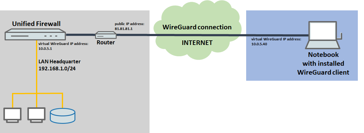
2) The Unified Firewall is connected to the Internet via an upstream router:
- A company wants its sales representatives to have access to the corporate network via an WireGuard client-to-site connection.
- The notebooks used by the sales representatives have the WireGuard client installed on them.
- The company headquarters has a Unified Firewall as the gateway and an upstream router for the Internet connection. The router has the fixed public IP address 81.81.81.1.
- The local network at the headquarters has the IP address range 192.168.1.0/24.
- The Unified Firewall uses the virtual IP adress 10.0.5.1 for the WireGuard connection, whereas the WireGuard client uses the virtual IP address 10.0.5.40.
Procedure:
The setup for scenarios 1 and 2 is basically the same. Scenario 2 additionally requires port forwarding to be set up on the upstream router (the default port for WireGuard is 51820, for additional WireGuard connections the port is incremented).
Configuring the WireGuard connections must be carried out in parallel on the Unified Firewall and on the software client (steps 1.1 and 1.2 as well as 2), since the public key must be stored on the Unified Firewall and in the software client. For the sake of clarity, however, the setup is described in separate parts of this document.
1) Configuring WireGuard on the Unified Firewall:
1.1) Configuring the WireGuard interface on the Unified Firewall:
A separate WireGuard interface has to be used for each WireGuard configuration (called WireGuard Connection). It is possible however, to enter several Peers in a WireGuard configuration.
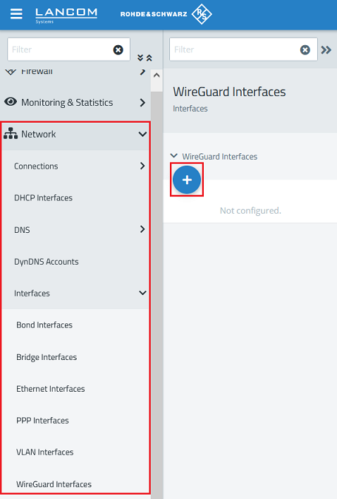
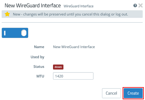
1.1.1) Connect to the web interface of the Unified Firewall and navigate to the menu Network → WireGuard Interfaces. Click the “+” icon to create a new WireGuard interface.
1.1.2) Click Create to generate the interface.
1.2) Configuring the WireGuard connection on the Unified Firewall:
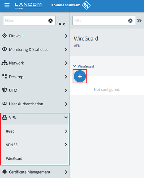
1.2.1) Go to the menu VPN → WireGuard and click the “+” icon to create a WireGuard connection.
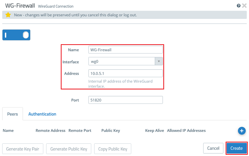
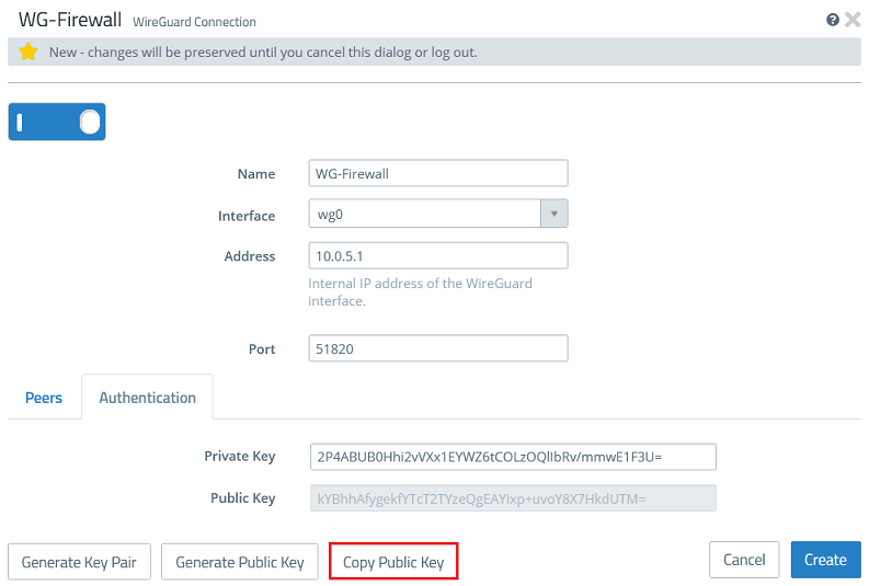
1.2.2) Modify the following parameters:
- Name: Enter a descriptive name for the WireGuard connection (in this example WG-Firewall).
- Interface: From the drop-down menu, select the WireGuard interface created in step 1.1.
- Address: Enter an IP address from an as yet unused IP address range (in this example 10.0.5.1).
The port automatically increments when multiple WireGuard connections are created.
1.2.3) Go to the tab Authentication and click the button Generate Key Pair. This automatically generates the private key and the public key.
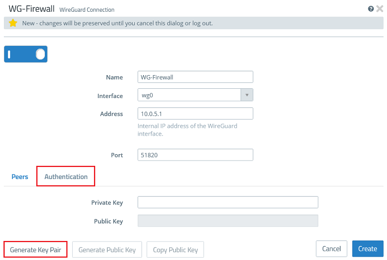
1.2.4) Click Copy Public Key and save it in a text file.
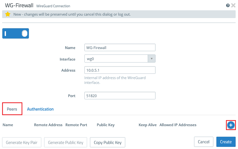
1.2.5) Go back to the tab Peers and click the “+” sign to specify the connection parameters for the remote site.
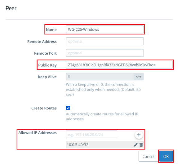
1.2.6) Modify the following parameters and click OK:
- Name: Enter a descriptive name for the connection to the remote site (in this example WG-C2S-Windows).
- Public Key: Enter the public key for the WireGuard Windows client copied in step 2.2.
- Allowed IP addresses: Enter the IP address of the WireGuard Windows client in CIDR notation (Classless Inter Domain Routing), which is to communicate with the local networks via the WireGuard connection (in this example 10.0.5.40/32).
It is possible to enter several Peers in a WireGuard configuration (they can be established at the same time). In doing so, multiple WireGuard clients can be connected without needing to set up a new configuration for each client.
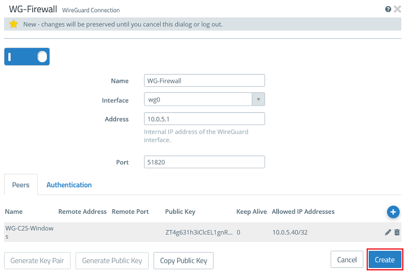
1.2.7) Then click Create.
1.3) Allow data traffic between the local network and the WireGuard client:
Repeat the following steps for any other local or remote network that is to communicate via the WireGuard tunnel.
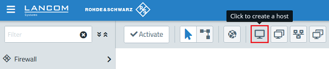
1.3.1) Click the icon to create a new host.
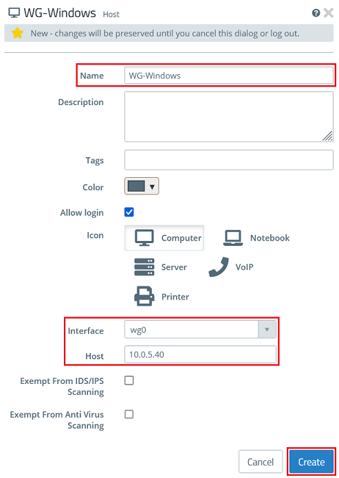
1.3.2) Modify the following parameters and then click Create:
- Name: Enter a descriptive name for the host (in this example WG-Windows).
- Interface: From the drop-down menu, select the WireGuard interface created in step 1.1.
- Host: Click in the box to display the IP address entered under Allowed IP addresses in step 1.2.6, and select it (in this example 10.0.5.40).
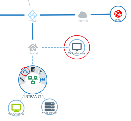
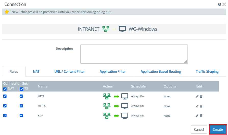
1.3.3) Click the object for the local network on the desktop (in this example INTRANET), select the connection tool, and click the object for the WireGuard host created in step 1.3.2.
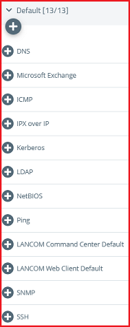
1.3.4) Add the protocols required for communication.
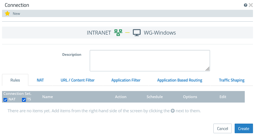
1.3.5) Click Create to generate the connection rules.
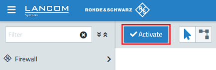
1.3.6) Finally, implement the changes by clicking Activate.
2) Configuring the WireGuard Windows client:
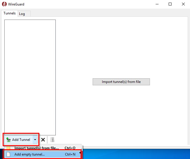
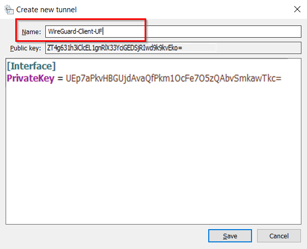
2.1) Start the WireGuard client in Windows and click Add Tunnel → Add empty tunnel.
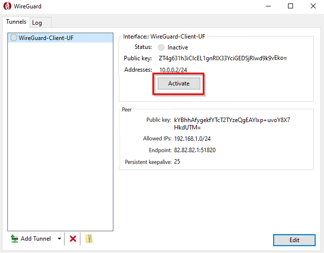
2.2) Enter a descriptive name for the tunnel (in this example WireGuard-Client-UF) and save the public key in a text file.
The private key and public key are generated automatically.
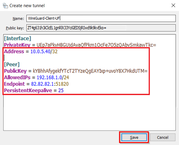
2.3) Complete the configuration file by inserting the template (see below) and adjusting the parameters. Then click Save:
- Address: Using CIDR notation, enter the IP address you specified for the WireGuard client in step 1.2.6 (in this example 10.0.5.40/32).
- PublicKey: Enter the public key for the Unified Firewall copied in step 1.2.4.
- AllowedIPs: Using CIDR notation, enter an IP network of the Unified Firewall that the WireGuard client communicates with (in this example 192.168.1.0/24). Multiple networks can also be entered by separating them with a comma (e.g. 192.168.1.0/24, 192.168.2.0/24).
- Endpoint: Enter the IP address or the DNS name of the Unified Firewall on the Internet along with the port used in the syntax <IP address or DNS name of the Unified Firewall on the Internet>:<WireGuard port> (in this example 81.81.81.1:51820).
- PersistentKeepalive: Enter the value 25 so that the WireGuard client maintains the connection for 25 seconds without data traffic.
Schablone zum Ergänzen der Konfigurations-Datei:
Address = <IP address>
[Peer]
PublicKey = <Public key>
AllowedIPs = <IP network>
Endpoint = <IP address>:<port>
PersistentKeepalive = 25
2.4) Finally, establish the connection by clicking Activate.