
Description:
This article describes how to set up a bridge in conjunction with VLAN on a LANCOM R&S®Unified Firewall.
VLANs cannot be stored directly in the bridge. The VLANs must instead be assigned to the Ethernet interfaces. The resulting VLAN interfaces can then be combined to a bridge.
If several VLANs are operated, the configuration quickly becomes very complicated because each VLAN must be assigned to all of the Ethernet interfaces in the bridge (i.e. two VLANs and two Ethernet interfaces will produce four VLAN interfaces). Furthermore, each VLAN requires the creation of a separate bridge group. This is necessary so that each VLAN can be assigned its own network.
Requirements:
- LCOS FX as of version 10.12 (download latest version)
- Web browser for configuring the Unified Firewall
The following browsers are supported:- Google Chrome
- Chromium
- Mozilla Firefox
Scenario:
- The Ethernet interfaces eth1 and eth2 should be combined to a bridge.
- The VLANs 100 and 200 should be used in the bridge.
- A separate network should be created for each VLAN.
- The VLAN 100 has the IP address range 192.168.100.0/24.
- The VLAN 200 has the IP address range 192.168.200.0/24.
Procedure:
1) Configuring the VLAN interfaces and the bridge:
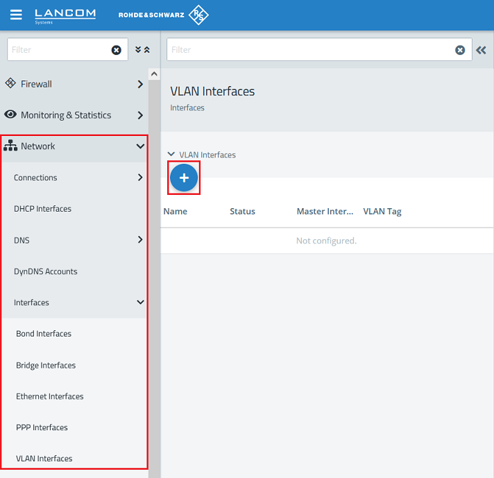
1.1) Using the web interface, navigate to the menu Network → Interfaces → VLAN Interfaces and click on the “+” icon to create a new VLAN interface.
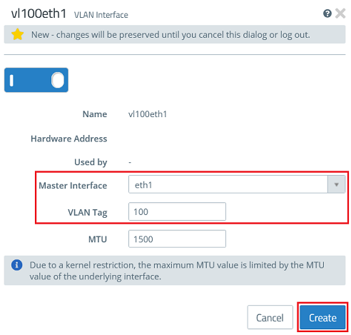
1.2) Create the VLAN interfaces for VLAN 100 on the Ethernet interfaces eth1 and eth2.
- For the first VLAN interface, enter the following parameters and click Create:
- Master Interface: Select the first Ethernet interface (in this case eth1).
- VLAN Tag: Enter the VLAN-ID 100.
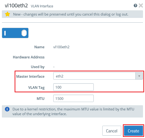
- For the second VLAN interface, enter the following parameters and click Create:
- Master Interface: Select the second Ethernet interface (in this case eth2).
- VLAN Tag: Enter the VLAN-ID 100.
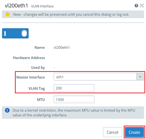
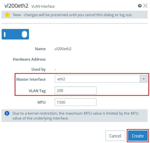
1.3) Create the VLAN interfaces for VLAN 200 on the Ethernet interfaces eth1 and eth2.
- For the third VLAN interface, enter the following parameters and click Create:
- Master Interface: Select the first Ethernet interface (in this case eth1).
- VLAN Tag: Enter the VLAN-ID 200.
- For the fourth VLAN interface, enter the following parameters and click Create:
- Master Interface: Select the second Ethernet interface (in this case eth2).
- VLAN Tag: Enter the VLAN-ID 200.
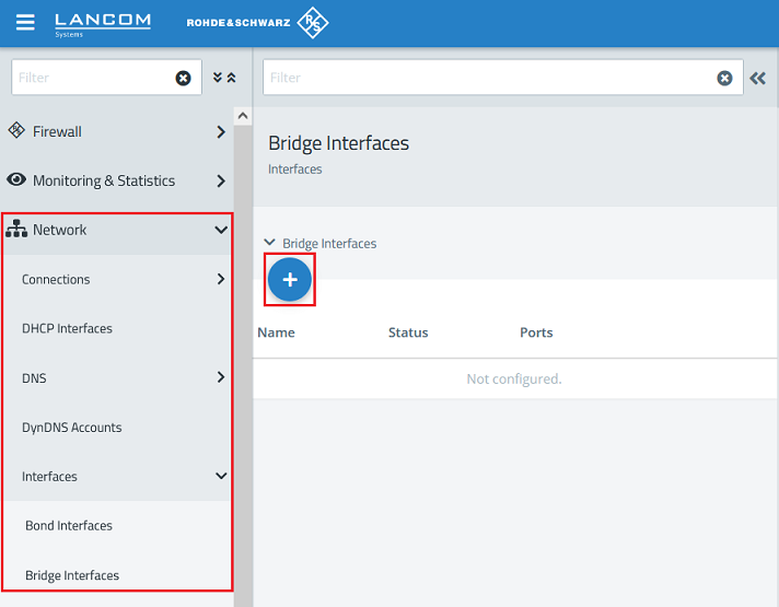
1.4) Navigate to the menu Network → Interfaces → Bridge Interfaces and click on the “+” icon to create a new bridge.
1.5) Create a bridge for VLAN 100 and, under Ports, select the VLAN interfaces created in step 1.2 (in this example vl100eth1 and vl100eth2).
Then click Create.

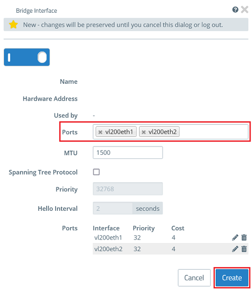
1.6) Create a bridge for VLAN 200 and, under Ports, select the VLAN interfaces created in step 1.3 (in this example vl200eth1 and vl200eth2).
Then click Create.
2) Creating the networks:
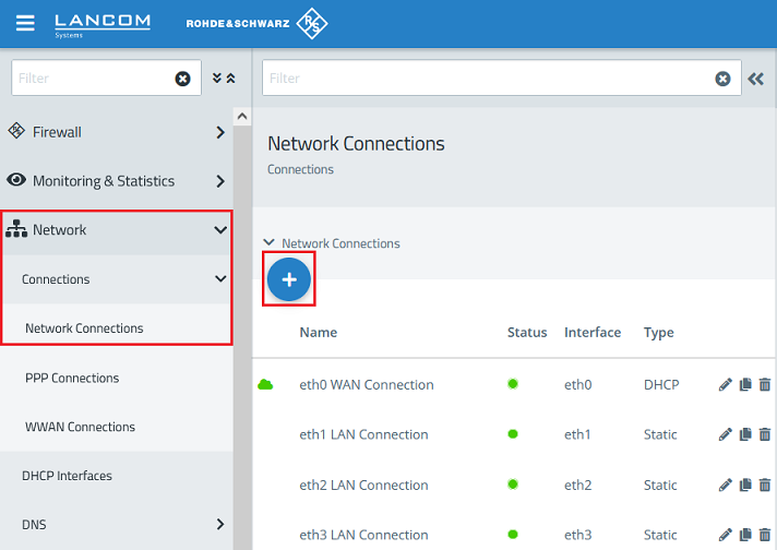
2.1) Change to the menu Network → Connections → Network Connections and click on the “+” icon to create a new connection.
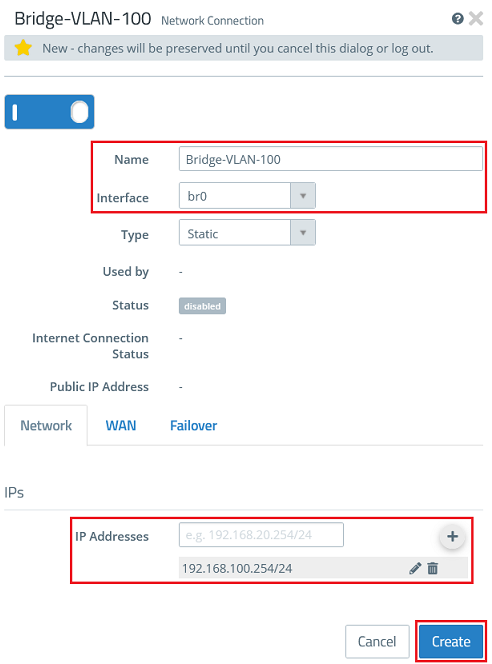
2.2) Create a new network connection for the VLAN 100 and modify the following parameters. Then click Create.
- Name: Enter a descriptive name for the network connection (in this example Bridge-VLAN-100).
- Interface: From the drop-down menu, select the bridge created in step 1.5 (in this case br0).
- IP Addresses: Enter the required IP address for this connection in CIDR notation, in this example 192.168.100.254/24.
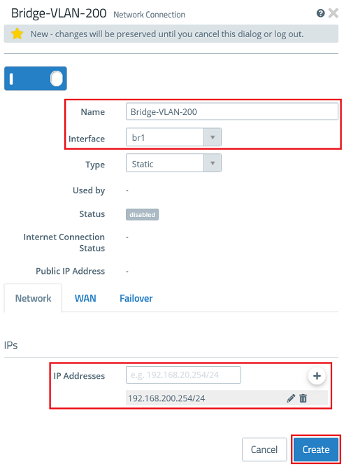
2.3) Create a new network connection for the VLAN 200 and modify the following parameters. Then click Create.
- Name: Enter a descriptive name for the network connection (in this example Bridge-VLAN-200).
- Interface: From the drop-down menu, select the bridge created in step 1.6 (in this case br1).
- IP Addresses: Enter the required IP address for this connection in CIDR notation, in this example 192.168.200.254/24.
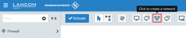
2.4) Click the create a network button to create desktop objects for the networks.
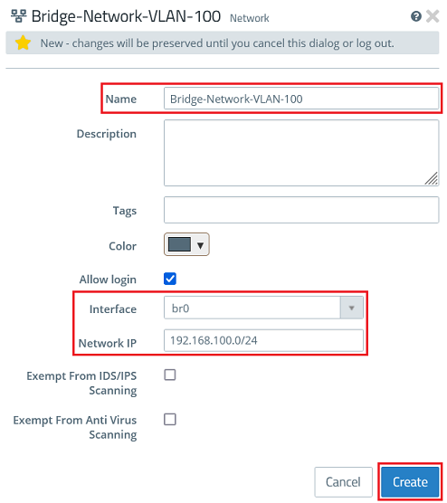
2.5) Create a desktop object for the network with VLAN 100 and modify the following parameters. Then click Create.
- Name: Enter a descriptive name for the network (in this example Bridge-Network-VLAN-100).
- Interface: From the drop-down menu, select the bridge created in step 1.5 (in this case br0).
- Network IP: Enter the network address of the network connection created in step 2.2 in CIDR notation (in this example 192.168.100.0/24).
2.6) Create a desktop object for the network with VLAN 200 and modify the following parameters. Then click Create.
- Name: Enter a descriptive name for the network (in this example Bridge-Network-VLAN-200).
- Interface: From the drop-down menu, select the bridge created in step 1.6 (in this case br1).
- Network IP: Enter the network address of the network connection created in step 2.3 in CIDR notation (in this example 192.168.200.0/24).

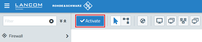
2.7) Finally, implement the changes by clicking Activate.
Further steps:
Below you will find suitable articles for further configuration: