
Description:
This document describes how to configure a cloud-managed hotspot with the LANCOM Management Cloud (LMC).
In this example scenario, LANCOM access points are operated behind an existing network infrastructure with components from other manufacturers. In this case, the hotspot is provided with the help of a so-called “overlay”. Here, the hotspot data transfer routes are overlaid on the existing connections.
This uses network address translation (NAT) to ensure that hotspot users and their data are securely isolated from the rest of the company's internal data streams. One of the access points then functions as a “NAT-AP”, i.e. it serves as a gateway for the remaining access points.
Please note that the routing performance of an access point is generally less than that of a router. This means, for example, that the achievable Wi-Fi speed is limited by the access point’s routing performance. We therefore strongly recommend using a high-performance access point as the “NAT-AP” (LX or LN series).
The gateway router and the switch do not have to support VLAN in order for this scenario to be implemented. This allows the use of an unmanaged switch, which is particularly useful in scenarios where there is no access to the network infrastructure (except for the access points).
When using an unmanaged switch, it must be able to pass on VLAN transparently.
When operating a managed switch, the hotspot VLAN ID must be configured on it accordingly.
How to configure a cloud-managed hotspot where all LANCOM devices are managed by the LMC is described in this knowledge base article.
How to configure a cloud-managed hotspot where the gateway router is not managed by the LMC is described in this knowledge base article.
Requirements:
- LCOS as of version 10.42 or LCOS LX as of version 5.30 (download current version)
- Access to the LANCOM Management Cloud (subject to charge)
- Any web browser for accessing the LANCOM Management Cloud
- Functional Wi-Fi network already configured in the LMC
The procedures described below are based on a fully functional network scenario with LANCOM access points that are managed exclusively by the LMC.
Scenario:
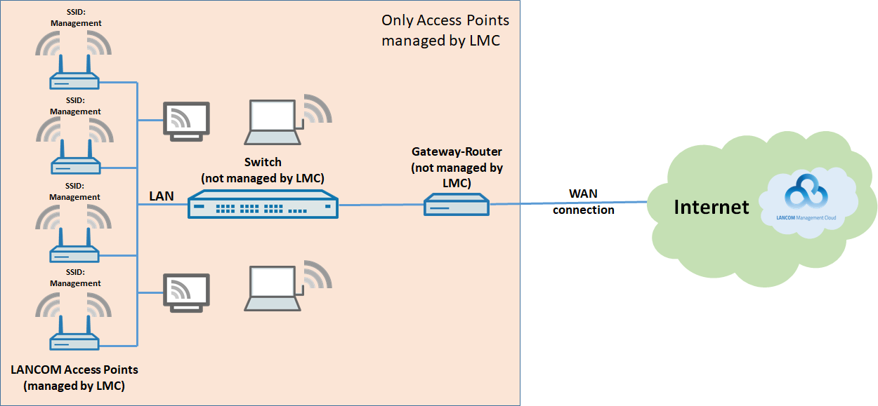
The Wi-Fi in a company is operated with LANCOM access points and managed by the LANCOM Management Cloud:
- Numerous LANCOM access points are used for the Wi-Fi, all of which are managed by the LMC.
- Furthermore, a switch and a third-party router are operated. These of course cannot be managed by the LMC.
- A local network is available to all employees.
- The existing LANCOM access points broadcast a Wi-Fi network with the SSID “Management”. This Wi-Fi can be used by all company employees.
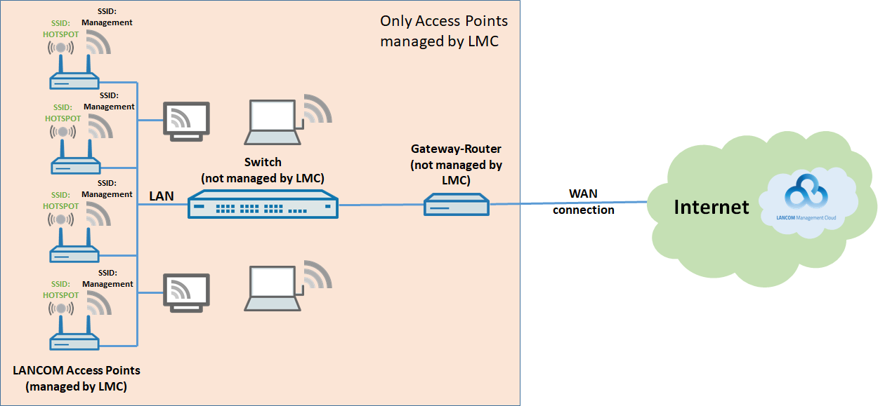
The existing scenario should be upgraded with Wi-Fi access for guests:
- An additional SSID should be broadcast by all access points (e.g. “HOTSPOT”).
- The guest Wi-Fi should be in its own local network that has no access to the company's management network and that offers only Internet access to users.
- There should be no communication between the Wi-Fi clients in the guest Wi-Fi.
Procedure:
1) Configuration steps in the LMC:
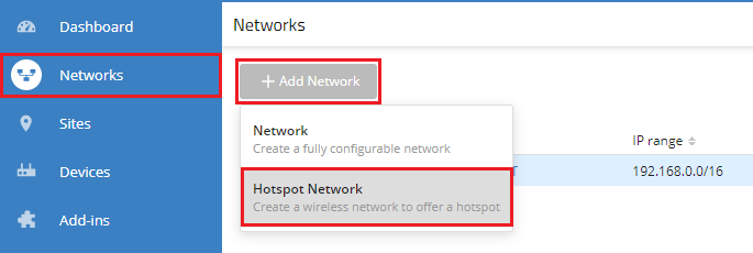
1.1) Open your LMC project, navigate to the menu Networks and click Add Network → Hotspot Network.
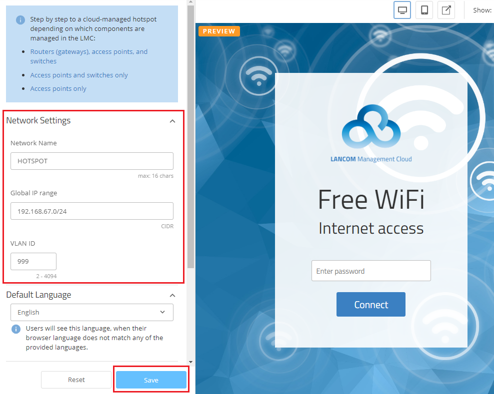
1.2) In the Network Settings section, set up the basic technical settings for the new hotspot network, and then click on Save:
- SSID Name: Enter a descriptive name for the broadcast SSID (e.g. HOTSPOT). This can be max. 16 characters long.
- Global IP range: If necessary adapt the IP address range to be used by the hotspot network. Enter the IP address range in CIDR notation (e.g. 172.16.0.0/24).
- VLAN ID: The VLAN ID is set to 999 by default. You can adapt this, if necessary (in the range from VLAN ID 2 to 4094).
You can define in the Authentication menu after what time a user is automatically logged out of the hotspot.
To ensure that the text on the splash page is displayed in English, your own text can be specified under Translations.
By default, the Wi-Fi hotspot is unencrypted. If preferred, you can also operate it with encryption by setting a Password under Authentication. This must then be entered by the guests when they log in.
Please note that it is not possible to use separate access credentials for individual users.
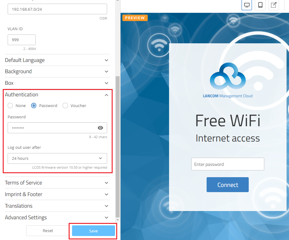
If you want to use voucher authentication, select the option provided. For a description of the configuration, see this Knowledge Base article.
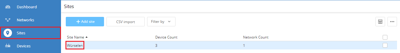
1.3) Go to the Sites menu and select the configured site.
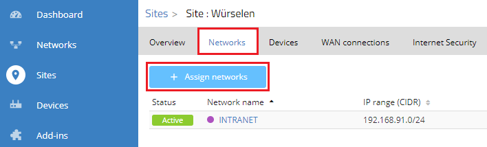
1.4) For the site, change to the Networks tab and click on Assign networks.
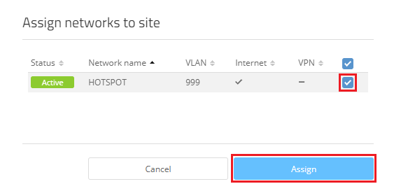
1.5) Choose the hotspot network created in step 1.2 and click Assign.
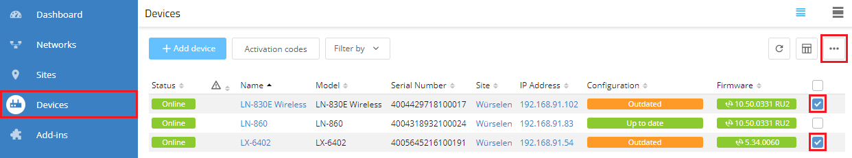
1.6) Go to the Devices menu, mark all access points that are assigned to the site and click on the dots icon in the upper right-hand corner.
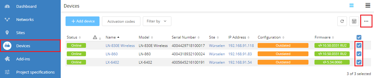
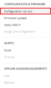
1.7) Click on Configuration roll out.
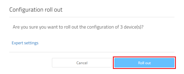
1.8) Confirm the prompt by clicking on Roll out.
2) Changing the “NAT-AP”:
The LMC selects the “NAT-AP” at random. In the interests of higher performance it may make sense to change this.
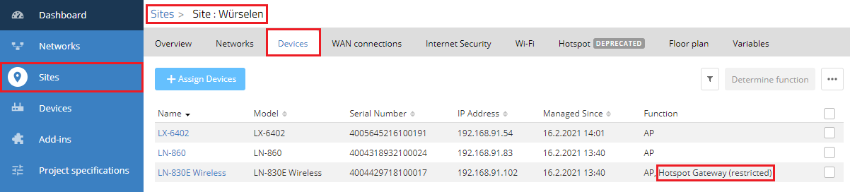
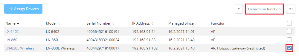
2.1) Use the Sites menu to go to the relevant site and then to the tab Devices.
The “NAT-AP” is marked with Hotspot Gateway (restricted).
2.2) Select the “NAT-AP” and click on Determine function.
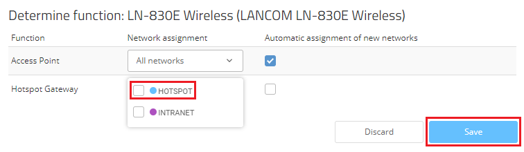
2.3) For the Hotspot Gateway, remove the hotspot network assigned to it and click on Save.
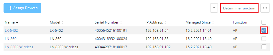
2.4) Select the access point that is to act as “NAT-AP” and click Determine function.
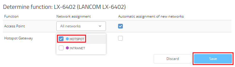
2.5) For the Hotspot Gateway, add the assigned hotspot network and click Save.
2.6) Go to the Devices menu, mark the access points that had a change of function (status Outdated) and click on the dots icon in the upper right-hand corner.
2.7) Click on Configuration roll out.